
A device and method for laterally applying ultrasonic energy based on a combination of rollers and stirring heads

A technology for applying devices and ultrasonic energy, which is applied in metal processing equipment, welding equipment, manufacturing tools, etc., can solve the problems of time lag, inability to fully exert the effect of ultrasonic vibration, and the inability to realize simultaneous coupling of ultrasonic softening effects of the mechanical action of the stirring head, etc. Achieve the effects of reducing friction, improving weld morphology, and promoting material migration

Active Publication Date: 2019-11-12
SHANDONG UNIV
View PDF9 Cites 0 Cited by
  • Summary
  • Abstract
  • Description
  • Claims
  • Application Information

AI Technical Summary

Problems solved by technology

However, in this scheme, the ultrasonic vibration is applied to the direct mode of the workpiece in front of the stirring head, which will cause the ultrasonic softening to occur earlier than the FSW thermal-mechanical process, and there is a time lag in the local action of the ultrasonic tool head and the stirring head on the workpiece, which cannot be realized Simultaneous coupling of the mechanical action of the stirring head and the ultrasonic softening effect, so that the role of ultrasonic vibration in improving welding quality cannot be fully utilized

Method used


Image

  • A device and method for laterally applying ultrasonic energy based on a combination of rollers and stirring heads
  • A device and method for laterally applying ultrasonic energy based on a combination of rollers and stirring heads
  • A device and method for laterally applying ultrasonic energy based on a combination of rollers and stirring heads

Examples


Embodiment Construction

[0028] It should be pointed out that the following detailed description is exemplary and intended to provide further explanation to the present application. Unless defined otherwise, all technical and scientific terms used herein have the same meaning as commonly understood by one of ordinary skill in the art to which this application belongs.

[0029] It should be noted that the terminology used here is only for describing specific implementations, and is not intended to limit the exemplary implementations according to the present application. As used herein, unless the context clearly dictates otherwise, the singular is intended to include the plural, and it should also be understood that when the terms "comprising" and / or "comprising" are used in this specification, they mean There are features, steps, operations, means, components and / or combinations thereof.

[0030] As described in the background technology, there are deficiencies in the prior art. In order to solve the...


PUM


Abstract

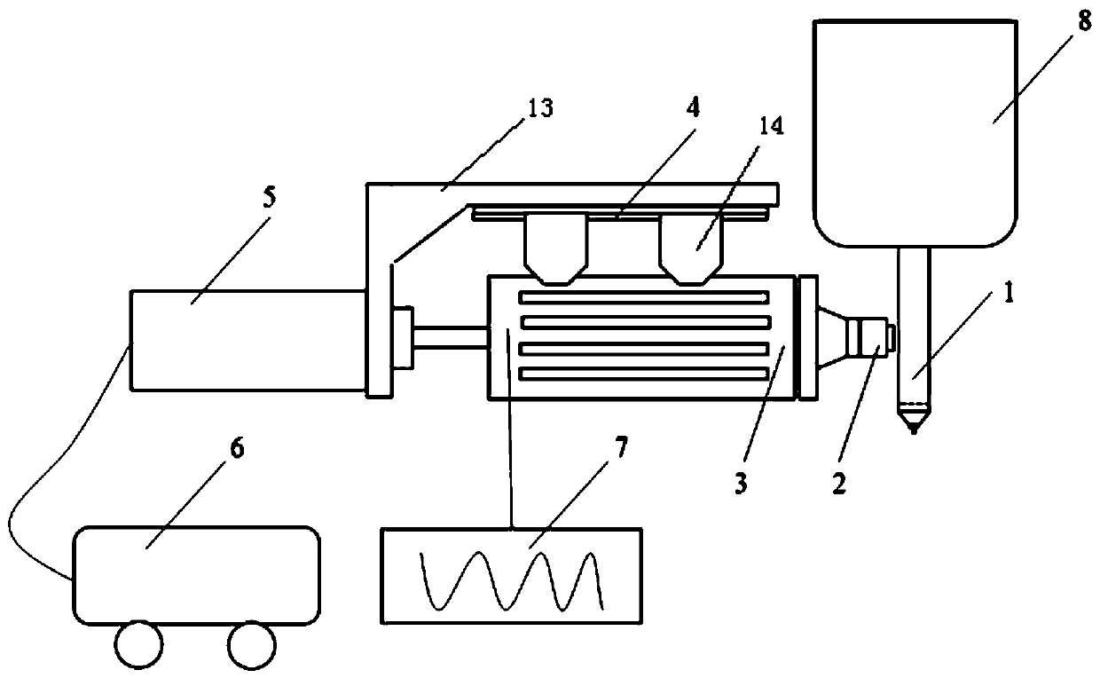
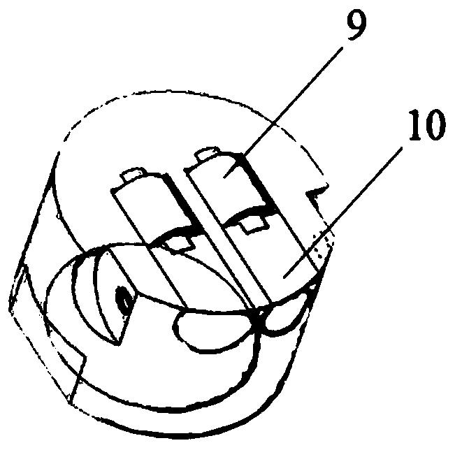
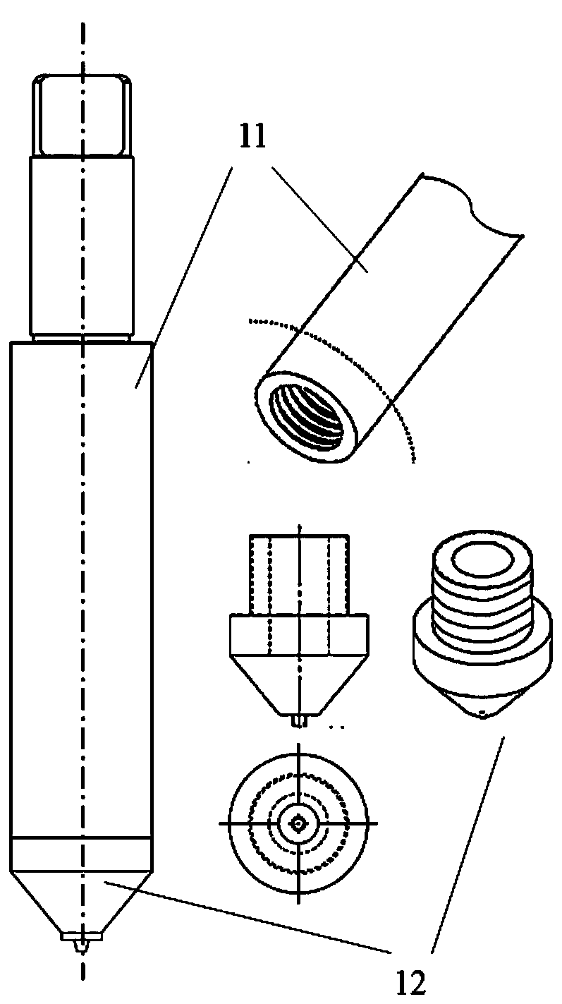
The invention discloses an ultrasonic energy transverse applying device and method based on rolling column and stirring head combination, solves the problem of time delay of ultrasonic vibration and amechanical effect of a stirring head or incapability of realizing effective coupling of the two in the prior art, and has the beneficial effects of improving plastic flowing of metal in the welding process and realizing synchronous coupling of a thermal effect of the stirring head and an ultrasonic softening effect. The ultrasonic energy transverse applying device based on rolling column and stirring head combination comprises a sleeve fixture; the sleeve fixture is connected with an ultrasonic generation mechanism; one end of the sleeve fixture is connected with a pushing mechanism, and a rolling column tool head is arranged at the other end; the stirring head for welding workpieces is arranged at the side part of the rolling column tool head; the axis direction of the stirring head is perpendicular to the axis direction of the rolling column tool head; the pushing mechanism drives the sleeve fixture to move towards the stirring head; and ultrasonic energy is transferred to the stirring head through contact between the rolling column tool head and the stirring head.

Description

technical field [0001] The invention relates to the field of friction stir welding, in particular to an ultrasonic energy lateral application device and method based on a combination of a roller and a stirring head. Background technique [0002] Friction Stir Welding (FSW) is a solid-phase welding technology that can obtain high-quality joints that are difficult to weld by conventional methods. It is currently mostly used in the field of aluminum alloy structure manufacturing. Conventional FSW relies on the frictional heat between the stirring head and the material to be welded and the heat generated by the plastic deformation of the material to soften the material to be welded. There are problems such as low welding speed and large welding load. The bearing capacity of the welding machine, the accuracy and rigidity of the welding fixture , The wear resistance of the mixing head puts forward very high requirements. The method of applying ultrasonic energy to the FSW process...

Claims


Application Information

Patent Timeline
Patent Type & Authority Patents(China)
IPC IPC(8): B23K20/26B23K20/12
CPCB23K20/122B23K20/26
Inventor 武传松丁伟萨辰·库玛尔陈姬
Owner SHANDONG UNIV
Learn More