
a relief valve

A pressure relief valve and valve body technology, which is applied in the field of pressure relief valves, can solve the problems of precise adjustment of pressure relief and large resistance, and achieve the effects of ensuring accuracy and adjustment efficiency, and reducing the impact of pressure oil

Active Publication Date: 2019-03-22
ZHENGZHOU RES INST FOR ABRASIVES & GRINDING CO LTD
View PDF6 Cites 0 Cited by
  • Summary
  • Abstract
  • Description
  • Claims
  • Application Information

AI Technical Summary

Problems solved by technology

[0005] The purpose of the present invention is to provide a pressure relief valve to solve the technical problem in the prior art that the pressure of the liquid medium directly acts on the control valve stem, resulting in relatively large resistance to pressure relief and precise adjustment under high pressure conditions.

Method used


Image

  • a relief valve
  • a relief valve
  • a relief valve

Examples


Embodiment Construction

[0017] Embodiments of the present invention will be further described below in conjunction with the accompanying drawings.

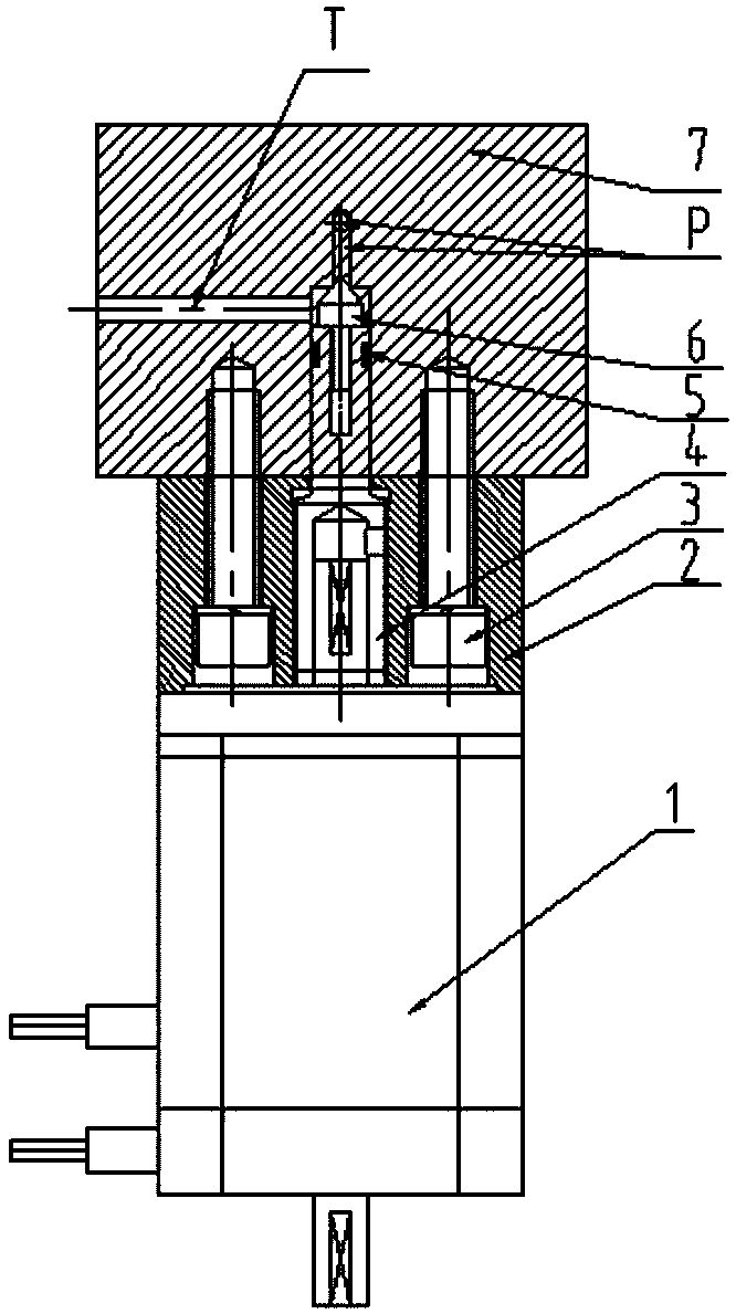
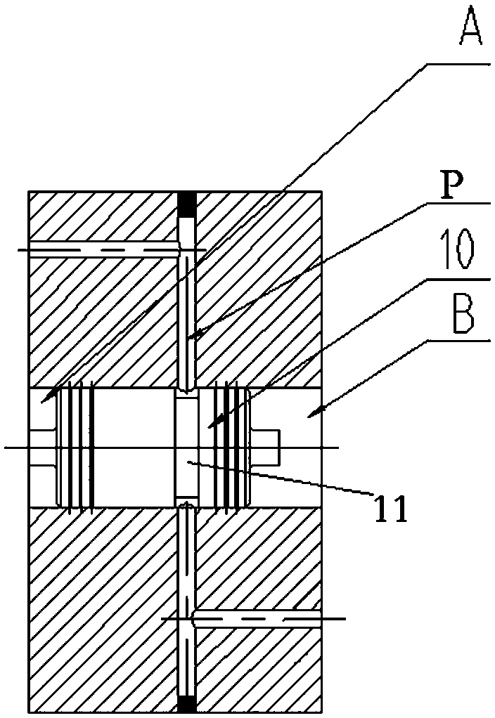
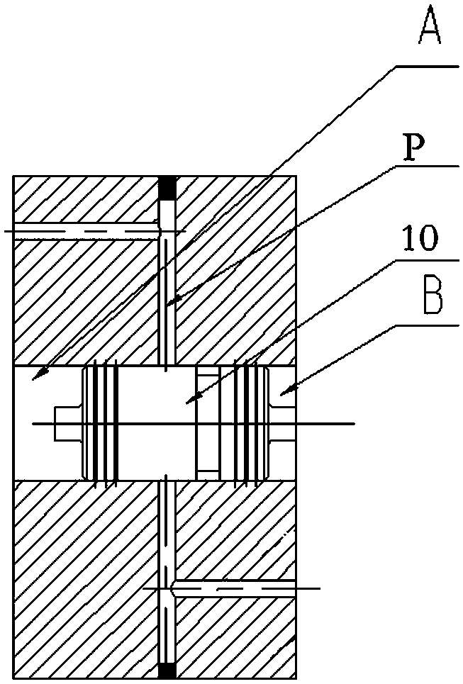
[0018] The specific embodiment of pressure relief valve provided by the present invention, such as Figure 1 to Figure 3 As shown, the pressure relief valve in this embodiment includes a valve body 7, which is provided with an oil inlet passage P, a pressure relief passage T and a valve seat arranged between the two passages. The valve body 7 is sealed and moved with a The valve stem is provided with a corresponding valve stem sealing ring 5, and the corresponding end of the valve stem is provided with a conical valve core 6 corresponding to the valve seat. During the reciprocating movement of the valve stem with the conical spool 6, This enables the conical valve core 6 to cooperate with the corresponding valve seat to form different openings of the valve port, corresponding to different pressure relief level requirements.

[0019] The valve body 7 is ...


PUM


Abstract

The invention relates to a decompression valve comprising a valve body. An oil inlet channel, a decompression channel and valve seats arranged between the oil inlet channel and the decompression channel are arranged on the valve body. A conical valve element is movably assembled in the valve body and corresponds to the valve seat. The valve body is further provided with a drive mechanism, wherein the drive mechanism is used for driving the conical valve element to move so as to enable the conical valve element to cooperate with the valve seat in the moving process to form different valve port opening degrees. The oil inlet channel is provided with an unblocking-blocking valve element used for controlling the oil inlet channel to be unblocked or blocked. When movement of the conical valve element needs to be utilized so as to adjust the decompression grade, the unblocking-blocking valve element is used for blocking the oil inlet channel firstly, a short-time or instant static environment can be formed, the impact, exerted by pressure oil, borne by the conical valve element in the adjustment process is effectively reduced, corresponding decompression adjustment is convenient to achieve, and the decompression adjustment precision and adjustment efficiency can be effectively guaranteed.

Description

technical field [0001] The present invention relates to a pressure relief valve. Background technique [0002] Synthetic equipment for synthetic diamond in my country is a six-sided top press. The pressure of the hydraulic press is as high as 100MPa, and a set of ultra-high pressure hydraulic system is correspondingly equipped. The main function of the ultra-high pressure hydraulic system is to provide high-pressure hydraulic oil during the pressing process of the hydraulic press, and to maintain the pressure during the diamond synthesis process. After the synthesis, the hydraulic system needs to unload the pressure to about 6MPa, and thus complete a work cycle. [0003] During the unloading process of the hydraulic system, the pressure relief speed and pressure relief control accuracy are crucial to the synthesis of diamonds. Improper pressure relief control will cause serious consequences, such as blasting, cracking hammers, and affecting the production and stability of sy...

Claims


Application Information

Patent Timeline
Patent Type & Authority Patents(China)
IPC IPC(8): F16K31/04F16K1/36F16K1/54
CPCF16K1/36F16K1/54F16K31/04
Inventor 古龙辉
Owner ZHENGZHOU RES INST FOR ABRASIVES & GRINDING CO LTD
Learn More