
An oscilloscope and its timing setting method and system in automatic acquisition mode

An automatic acquisition and oscilloscope technology, applied in the input/output process of instruments, data processing, calculation, etc., can solve the problems that the oscilloscope cannot trigger stably, the number of signal frames decreases, etc., and achieve the effect of stable triggering and improving acquisition efficiency

Active Publication Date: 2020-04-14
SHENZHEN CITY SIGLENT TECH
View PDF14 Cites 0 Cited by
  • Summary
  • Abstract
  • Description
  • Claims
  • Application Information

AI Technical Summary

Problems solved by technology

There are two disadvantages in this timer setting method: 1. When the time base is small (such as 10ns), the value T of the timer is also very small. If the probability that the input signal meets the trigger condition is very low, the oscilloscope will not be able to Stable trigger; 2. When the time base is large (such as 10ms), the value T of the timer is also very large. If the input signal does not meet the trigger condition at all, the number of signal frames that can be collected per unit time will be greatly reduced.

Method used


Image

  • An oscilloscope and its timing setting method and system in automatic acquisition mode
  • An oscilloscope and its timing setting method and system in automatic acquisition mode
  • An oscilloscope and its timing setting method and system in automatic acquisition mode

Examples


Embodiment Construction

[0031] The present invention will be further described in detail below through specific embodiments in conjunction with the accompanying drawings.

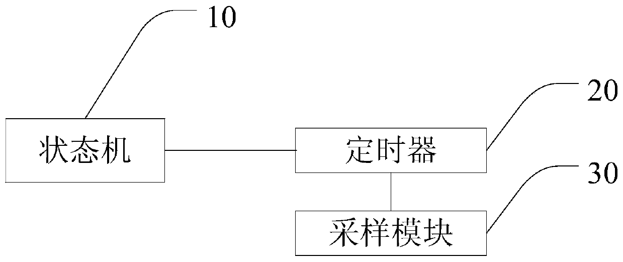
[0032] The present invention uses a state machine to detect the trigger signal, and the detection cycle of each state is different, and then determines how much the timer should be set according to the current state and whether the trigger signal appears in the current state.

[0033] Specifically, the present invention provides an oscilloscope, which includes a timing setting system under the automatic acquisition mode (AUTO), please refer to image 3 and Figure 4 , the timing setting system includes: a state machine 10 with n states, a timer 20 and a sampling module 30, wherein n is an integer greater than 2.

[0034] The n states of the state machine 10 are numbered as first, second, ..., nth, the first state is the lowest numbered state, and the nth state is the highest numbered state. The first state corresponds to a timin...


PUM


Abstract

The invention discloses an oscilloscope and a timing setting method and system thereof under an automatic collection mode. The system comprises a state machine which sets n pieces of states, and a timer, wherein a first state corresponds to timing time and a serial number progressive increase detection period; the nth state corresponds to the timing time and a serial number progressive decrease detection period; other states independently correspond to the timing time, the serial number progressive increase detection period and the serial number progressive decrease detection period; the timing time of the first state to an (n-1)th state progressively increases in sequence; the timing time of the first state is greater than the nth state; when a trigger signal is not detected in the serial number progressive increase detection period of a current state, an adjacent high serial number state is entered; when a plurality of trigger signals are detected in the serial number progressive decrease detection period of the current state, an adjacent low serial number state is entered; and therefore, according to the timing time of the current state of the state machine, timing sampling is carried out. Therefore, the timing time of the timing sample is adaptively regulated, and the stable trigger of a waveform is realized.

Description

technical field [0001] The invention relates to the field of oscilloscopes, in particular to an oscilloscope and a timing setting method and system in an automatic acquisition mode thereof. Background technique [0002] When doing modern electronic design, engineers need to select appropriate trigger conditions according to the characteristics of the electronic signal transmission they are concerned about, and at the same time use an oscilloscope to collect waveforms near the trigger event they are interested in for analysis. In actual design, the engineer does not know whether the current input signal satisfies the trigger condition selected by him, so the current oscilloscope provides a working mode, that is, automatic acquisition mode (AUTO). In this mode, if there is a potential trigger event that meets the trigger conditions, the oscilloscope can collect and display the waveforms near the trigger event and analyze them; if there is no trigger event that meets the condit...

Claims


Application Information

Patent Timeline
Patent Type & Authority Patents(China)
IPC IPC(8): G06F3/05
CPCG06F3/05
Inventor 李振军王永添郑文明宋民
Owner SHENZHEN CITY SIGLENT TECH
Learn More