Glass cupping jar inner wall cleaning equipment for medical cupping jars

A technology of inner wall cleaning and cupping, which is applied in the field of glass cupping inner wall cleaning equipment, can solve the problems of insufficient cleaning, time-consuming and laborious cleaning process, and slow cleaning speed, etc.

Inactive Publication Date: 2017-08-29
赣州清亦华科科技有限公司
View PDF5 Cites 15 Cited by
  • Summary
  • Abstract
  • Description
  • Claims
  • Application Information

AI Technical Summary

Problems solved by technology

[0007] In order to overcome the disadvantages of insufficient cleaning, slow cleaning speed, and time-consuming and labor-intensive cleaning process when cleaning glass cupping jars for cupping, the technical problem to be s...

Method used


Image

  • Glass cupping jar inner wall cleaning equipment for medical cupping jars
  • Glass cupping jar inner wall cleaning equipment for medical cupping jars
  • Glass cupping jar inner wall cleaning equipment for medical cupping jars

Examples


Embodiment 1

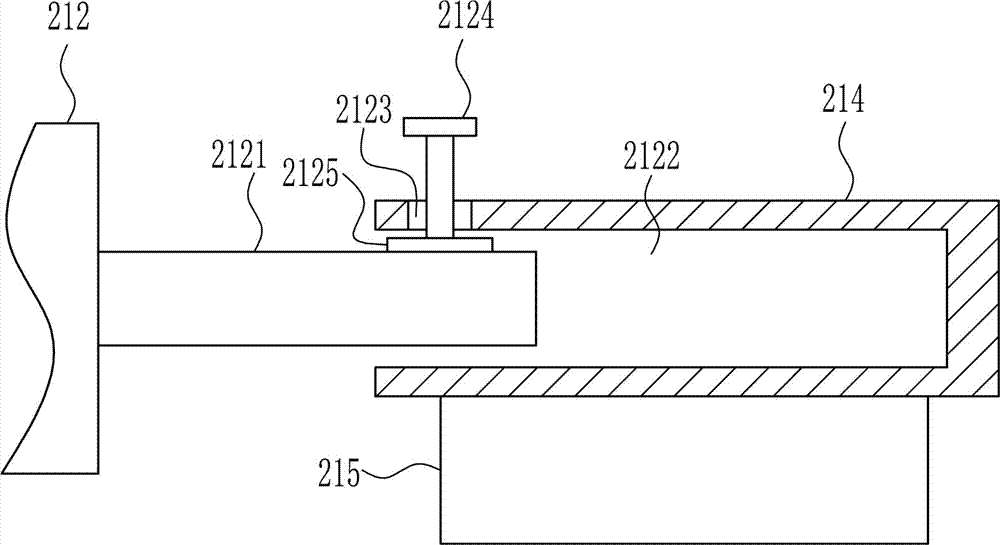
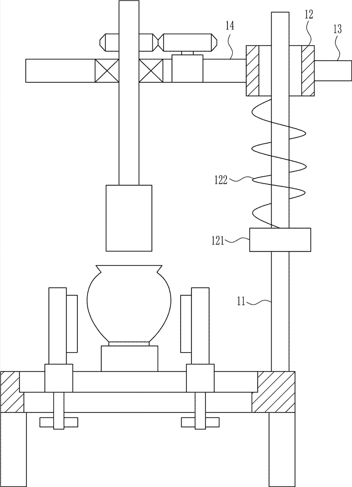
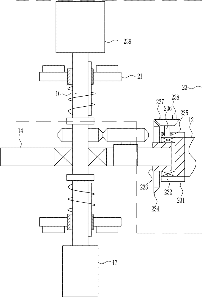
[0039] A glass cupping tank inner wall cleaning equipment for medical cupping, such as Figure 1-8 As shown, it includes a pillar 1, a mounting plate 2, a slide rail 3, a slider 4, a splint 5, a rubber block 6, a first screw rod 8, a first nut 9, a placement block 10, a guide rail 11, a guide sleeve 12, and a push handle 13. Support plate 14, first bearing seat 15, first rotating rod 16, first sponge block 17, first circular gear 18, first motor 19 and second circular gear 20, the upper ends of two pillars 1 are welded The mounting plate 2 is installed in the same way, and the upper middle part of the mounting plate 2 is installed with a slide rail 3 through bolt connection. The slide rail 3 is slidably connected with two sliders 4, and the upper side of the slider 4 is installed by welding. There is a splint 5, the inner side of the splint 5 is connected with a rubber block 6, the lower side of the mounting plate 2 has a slot 7, and the lower side of the slider 4 is installed...

Embodiment 2

[0041] A glass cupping tank inner wall cleaning equipment for medical cupping, such as Figure 1-8 As shown, it includes a pillar 1, a mounting plate 2, a slide rail 3, a slider 4, a splint 5, a rubber block 6, a first screw rod 8, a first nut 9, a placement block 10, a guide rail 11, a guide sleeve 12, and a push handle 13. Support plate 14, first bearing seat 15, first rotating rod 16, first sponge block 17, first circular gear 18, first motor 19 and second circular gear 20, the upper ends of two pillars 1 are welded The mounting plate 2 is installed in the same way, and the upper middle part of the mounting plate 2 is installed with a slide rail 3 through bolt connection. The slide rail 3 is slidably connected with two sliders 4, and the upper side of the slider 4 is installed by welding. There is a splint 5, the inner side of the splint 5 is connected with a rubber block 6, the lower side of the mounting plate 2 has a slot 7, and the lower side of the slider 4 is installed...

Embodiment 3

[0044] A glass cupping tank inner wall cleaning equipment for medical cupping, such as Figure 1-8 As shown, it includes a pillar 1, a mounting plate 2, a slide rail 3, a slider 4, a splint 5, a rubber block 6, a first screw rod 8, a first nut 9, a placement block 10, a guide rail 11, a guide sleeve 12, and a push handle 13. Support plate 14, first bearing seat 15, first rotating rod 16, first sponge block 17, first circular gear 18, first motor 19 and second circular gear 20, the upper ends of two pillars 1 are welded The mounting plate 2 is installed in the same way, and the upper middle part of the mounting plate 2 is installed with a slide rail 3 through bolt connection. The slide rail 3 is slidably connected with two sliders 4, and the upper side of the slider 4 is installed by welding. There is a splint 5, the inner side of the splint 5 is connected with a rubber block 6, the lower side of the mounting plate 2 has a slot 7, and the lower side of the slider 4 is installed...


PUM


Abstract

The invention relates to medical equipment, in particular to glass cupping jar inner wall cleaning equipment for medical cupping jars. The glass cupping jar inner wall cleaning equipment for medical cupping jars is comprehensive in cleaning and high in cleaning speed; and time and labor are saved in a cleaning process. In order to solve the technical problem, the invention provides the glass cupping jar inner wall cleaning equipment for medical cupping jars. The glass cupping jar inner wall cleaning equipment for medical cupping jars comprises braces, a mounting plate, a sliding track, sliders, clamping plates, rubber blocks, first screws, first nuts, a placement block, a guide track, a guide sleeve, a pushing handle, a supporting plate and the like. The mounting plate is mounted at upper ends of the two braces in a welded mode, the sliding track is mounted in the middle of the upper side of the inside of the mounting plate in a bolt connection mode, the inside of the sliding track is slidably connected with the two sliders, and each clamping plate is mounted on the upper side of the corresponding slider in a welded mode. The glass cupping jar inner wall cleaning equipment for medical cupping jars is comprehensive in cleaning and high in cleaning speed, and time and labor are saved in a cleaning process.

Description

technical field [0001] The invention relates to a medical device, in particular to a glass cupping inner wall cleaning device for medical cupping. Background technique [0002] Cupping is a kind of tool that uses cups and jars to remove the air in it by heat to generate negative pressure, so that it can be absorbed on the skin and cause blood stagnation. Ancient doctors used it to suck blood and drain pus when treating sores and abscesses, and later expanded its application to internal diseases such as tuberculosis and rheumatism. After the founding of the People's Republic of China, due to the continuous improvement of methods, cupping therapy has a new development, further expands the scope of treatment, and becomes an important therapy in acupuncture and moxibustion. [0003] Cupping is a common tool for cupping therapy. It uses methods such as burning, sucking, and squeezing to remove the air in the cup and create a negative pressure, so that the cup can be adsorbed on ...

Claims


Application Information

Patent Timeline
IPC IPC(8): B08B9/087B08B13/00
CPCB08B9/087B08B13/00
Inventor 不公告发明人
Owner 赣州清亦华科科技有限公司
Why Eureka
Try Eureka