Fast cutting off device for hardware parts

A technology for parts and equipment, applied in the field of fast cutting equipment for hardware parts, can solve the problems of poor cutting effect, cumbersome machine, slow cutting speed, etc.

Active Publication Date: 2017-08-29
NANTONG KAIDI AUTOMATIC MACHINERY
View PDF8 Cites 17 Cited by
  • Summary
  • Abstract
  • Description
  • Claims
  • Application Information

AI Technical Summary

Problems solved by technology

[0006] In order to overcome the disadvantages of heavy, slow cutting speed and poor cutting effect of the current hardware parts cutting machine, the technical problem to be solved by the present invention is to provide a circuit board production machine that is lightweight, fast cutting and good cutting effect. Clad Steel Cutting Equipment

Method used


Image

  • Fast cutting off device for hardware parts
  • Fast cutting off device for hardware parts
  • Fast cutting off device for hardware parts

Examples


Embodiment 1

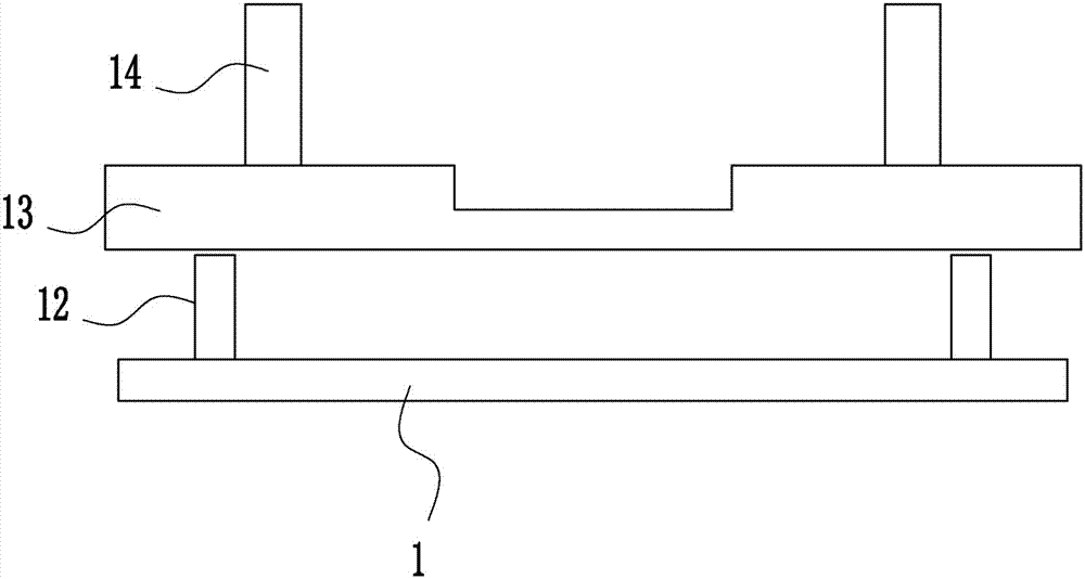
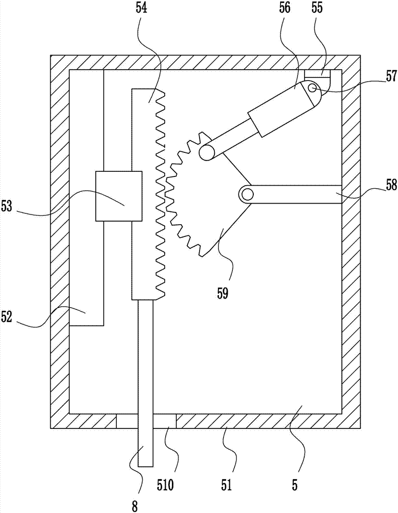
[0038] A fast cutting device for hardware parts, such as Figure 1-7 As shown, it includes a bottom plate 1, a first guide rod 2, a first guide sleeve 3, a moving rod 4, a lifting device 5, a top plate 6, a moving device 7, a lifting rod 8, a mounting rod 9, a second motor 10, and a blade 11 , the first bracket 12, the placing table 13, the fixing device 14, the swinging device 15, the hose 16, the nozzle 17, the air pump 18, the first mounting plate 19 and the mounting seat 20, and the left and right sides of the bottom plate 1 are symmetrically welded with the first A guide rod 2, a top plate 6 is welded on the top of the two first guide rods 2, a lifting device 5 is arranged in the middle of the bottom of the top plate 6, a lifting rod 8 is connected to the bottom of the lifting device 5, and a moving plate is welded on the bottom end of the lifting rod 8. The first guide rod 2 on the side and the first guide rod 2 on the right are both slidingly connected with the first gu...

Embodiment 2

[0040] A fast cutting device for hardware parts, such as Figure 1-7 As shown, it includes a bottom plate 1, a first guide rod 2, a first guide sleeve 3, a moving rod 4, a lifting device 5, a top plate 6, a moving device 7, a lifting rod 8, a mounting rod 9, a second motor 10, and a blade 11 , the first bracket 12, the placing table 13, the fixing device 14, the swinging device 15, the hose 16, the nozzle 17, the air pump 18, the first mounting plate 19 and the mounting seat 20, and the left and right sides of the bottom plate 1 are symmetrically welded with the first A guide rod 2, a top plate 6 is welded on the top of the two first guide rods 2, a lifting device 5 is arranged in the middle of the bottom of the top plate 6, a lifting rod 8 is connected to the bottom of the lifting device 5, and a moving plate is welded on the bottom end of the lifting rod 8. The first guide rod 2 on the side and the first guide rod 2 on the right are both slidingly connected with the first gu...

Embodiment 3

[0043] A fast cutting device for hardware parts, such as Figure 1-7 As shown, it includes a bottom plate 1, a first guide rod 2, a first guide sleeve 3, a moving rod 4, a lifting device 5, a top plate 6, a moving device 7, a lifting rod 8, a mounting rod 9, a second motor 10, and a blade 11 , the first bracket 12, the placing table 13, the fixing device 14, the swinging device 15, the hose 16, the nozzle 17, the air pump 18, the first mounting plate 19 and the mounting seat 20, and the left and right sides of the bottom plate 1 are symmetrically welded with the first A guide rod 2, a top plate 6 is welded on the top of the two first guide rods 2, a lifting device 5 is arranged in the middle of the bottom of the top plate 6, a lifting rod 8 is connected to the bottom of the lifting device 5, and a moving plate is welded on the bottom end of the lifting rod 8. The first guide rod 2 on the side and the first guide rod 2 on the right are both slidingly connected with the first gu...


PUM


Abstract

The invention relates to a cutting off device, in particular to a fast cutting off device for hardware parts. The invention solves the technical problem of providing a cutting device for a covering steel plate for production of a circuit board, which is light and handy, fast in cutting off and good in cutting off effect. In order to solve the technical problem above, the invention provides such a fast cutting off device for hardware parts, which comprises a bottom plate, first guide rods, first guide covers, a moving rod, a lifting device, a top plate, a moving device, a lifting rod, a mounting rod, a second motor, a blade, first supports, and the like; the first guide rods are symmetrically welded on the left side and the right side of the top of the bottom plate, the top plate is welded on the top ends of the two first guide rods, the middle of the bottom of the top plate is provided with the lifting device, and the bottom of the lifting device is connected to the lifting rod. By controlling the lifting device to move up and down, the blade is controlled in an optimal position, such that the cutting off effect is better, and by driving the blade to move left and right through the moving device, the cutting off is more thorough.

Description

technical field [0001] The invention relates to a cutting device, in particular to a fast cutting device for hardware parts. Background technique [0002] Hardware: traditional hardware products, also known as "hardware". Refers to the five metals of gold, silver, copper, iron, and tin. After manual processing, it can be made into works of art or metal devices such as knives and swords. Hardware in modern society is more extensive, such as hardware tools, hardware parts, daily hardware, construction hardware and security supplies. Most hardware products are not final consumer goods. [0003] Components During mechanical assembly, these parts are first assembled into components (component assembly) before entering the final assembly. Some components (called subassemblies) are also assembled with other components and parts to form larger assemblies before going into the final assembly. A larger component that is assembled from several sub-components and has independent fu...

Claims


Application Information

Patent Timeline
Patent Type & Authority Applications(China)
IPC IPC(8): B23D79/00B23Q11/00
CPCB23D79/00B23Q11/005
Inventor 不公告发明人
Owner NANTONG KAIDI AUTOMATIC MACHINERY
Why Eureka
Try Eureka