Clamp for concave workpiece

A workpiece fixture, concave technology, applied in the direction of manufacturing tools, metal processing machinery parts, clamping, etc., can solve the problems of inability to clamp, position, inappropriate flat clamps, and inability to directly tighten, and achieve high precision and good effect. Effect

Inactive Publication Date: 2017-08-29
CHENGDU HONGYU TIMES TECH CO LTD
View PDF0 Cites 0 Cited by
  • Summary
  • Abstract
  • Description
  • Claims
  • Application Information

AI Technical Summary

Problems solved by technology

[0002] When processing large machine tool parts, considering the weight and shape of the workpiece, the workpiece is generally a blank (cast iron) during clamping and positioning, and its surface size is complex and irregular. Therefore, clamping and positioning are difficult, and there are many clip defect
[0003] Under normal circumstances, the clamping surface of the fixture is generally flat, which can provide a large clamping force. When the clamping surface is an arc surface, it cannot be directly tightened, because the surface is easily deformed by force when the arc surface is directly tightened. , the plane fixture is obviously not suitable, and cannot be clamped and positioned accurately

Method used


Image

  • Clamp for concave workpiece

Examples


Embodiment Construction

[0012] The present invention will be further described below in conjunction with the accompanying drawings.

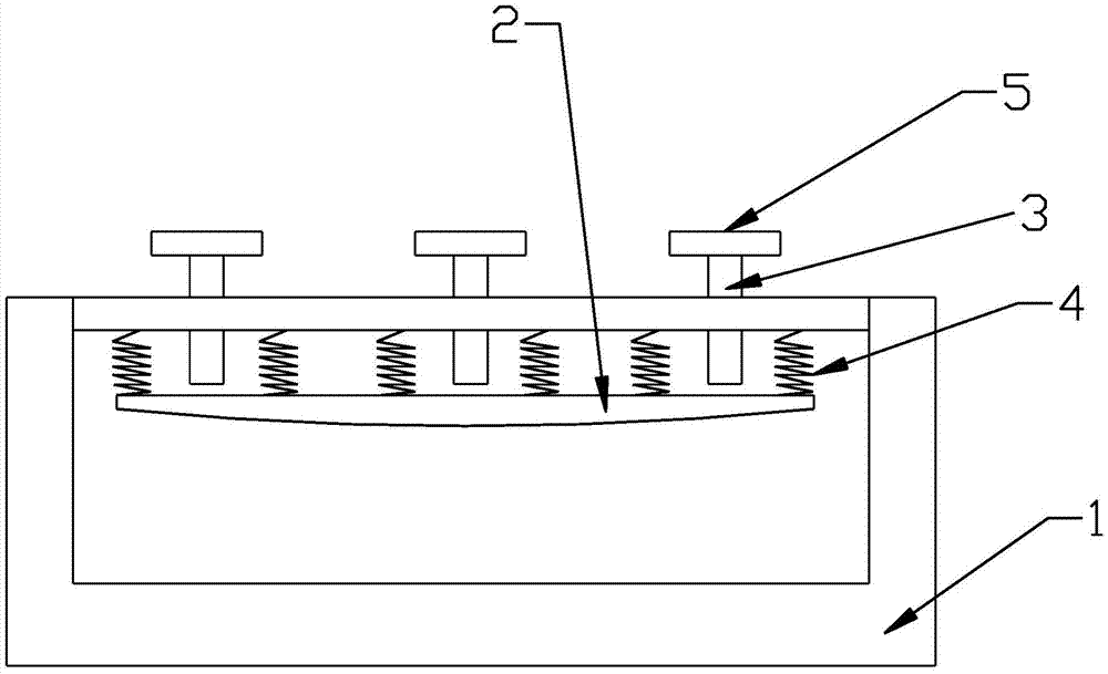
[0013] Such as figure 1 As shown, the present invention provides a concave workpiece fixture, including a base 1, an arc-shaped pressing plate 2, and a screw rod 3. The base 1 is a frame structure, and the arc-shaped pressing plate 2 has an arc surface that fits with the clamping surface of the workpiece. And the arc-shaped pressing plate 2 is arranged inside the base 1, a spring 4 is connected between the arc-shaped pressing plate 2 and the top plate of the base 1, the screw rod 3 is threadedly connected with the top plate of the base 1, and the outer end of the screw rod 3 A wrench 5 is provided, and the inner end is offset against the arc-shaped pressing plate 2 .

[0014] Further, in the above technical solution, the wrench 5 is provided with anti-skid lines.

[0015] Further, in the above technical solution, there are three screws 3 .

[0016] Further, in the a...


PUM


Abstract

The invention relates to a clamp for a concave workpiece. The clamp is characterized by comprising a base, an arc-shaped pressing plate and screw rods; the base is of a frame structure; the arc-shaped pressing plate is provided with an arc surface which is attached to the clamping surface of the workpiece and is arranged inside the base; springs are connected between the arc-shaped pressing plate and a top plate of the base; the screw rods are in threaded connection with the top plate of the base; and spanners are arranged at the outer ends of the screw rods, and the inner ends of the screw rods abut against the arc-shaped pressing plate. According to the technical scheme, the clamp for the concave workpiece has the advantages of being high in clamping and positioning precision and good in effect.

Description

technical field [0001] The invention relates to the technical field of clamps, in particular to a concave workpiece clamp. Background technique [0002] When processing large machine tool parts, considering the weight and shape of the workpiece, the workpiece is generally a blank (cast iron) during clamping and positioning, and its surface size is complex and irregular. Therefore, clamping and positioning are difficult, and there are many clip defect. [0003] Under normal circumstances, the clamping surface of the fixture is generally flat, which can provide a large clamping force. When the clamping surface is an arc surface, it cannot be directly tightened, because the surface is easily deformed by force when the arc surface is directly tightened. , the plane fixture is obviously not suitable, and it cannot be clamped and positioned accurately. How to make the concave-convex surface of the blank workpiece not affect the clamping and positioning, and keep the positioning ...

Claims


Application Information

Patent Timeline
Patent Type & Authority Applications(China)
IPC IPC(8): B23Q3/06
CPCB23Q3/062
Inventor 陈魏凌前武
Owner CHENGDU HONGYU TIMES TECH CO LTD
Why Eureka
Try Eureka