A cloth tensioning mechanism

A tensioning mechanism and fabric technology, applied in textiles and papermaking, fabric elongation, fabric surface trimming, etc., can solve the problems of reducing the degree, affecting the quality of the fabric, heating up, etc., so as to improve the tensioning efficiency and improve the quality of the fabric. , the effect of continuous tension

Active Publication Date: 2022-01-18
清远市诚鸿纺织有限公司
View PDF11 Cites 0 Cited by
  • Summary
  • Abstract
  • Description
  • Claims
  • Application Information

AI Technical Summary

Problems solved by technology

The cloth passes through the support roller and the opening roller in turn, and the opening roller drives it to rotate through the driving mechanism. At this time, the opening pattern of the spiral structure opens the cloth to the edge direction, so as to achieve the purpose of allowing the cloth to open, so that the cloth When stretching, the two sides of the fabric will not shrink too much. In addition, the open pattern will be extended to both ends in the opposite direction, so that the fabrics on both sides can be opened, so that the degree of fabric shrinkage inward is reduced. Small, so that the overall width of the cloth remains basically unchanged, but in the process of opening the cloth by the opening roller in this device, the cloth is spread horizontally by using the rotation direction of the opening pattern on the opening roller, and the gap between the opening pattern and the cloth There will be friction between them, causing the local temperature of the fabric to heat up rapidly, affecting the quality of the fabric

Method used


Image

  • A cloth tensioning mechanism
  • A cloth tensioning mechanism
  • A cloth tensioning mechanism

Examples


Embodiment

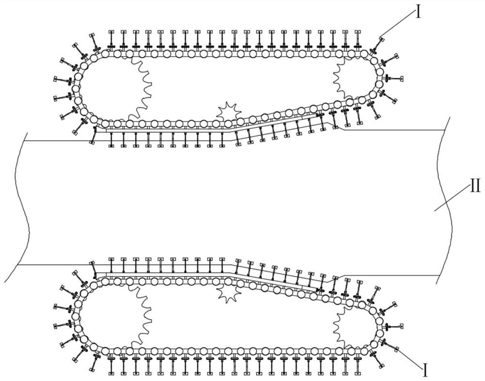
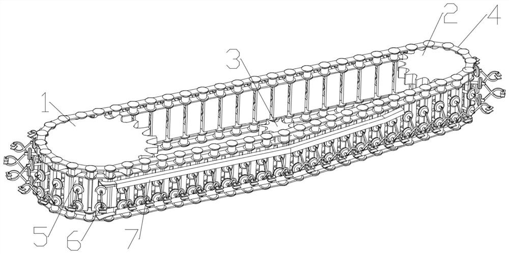
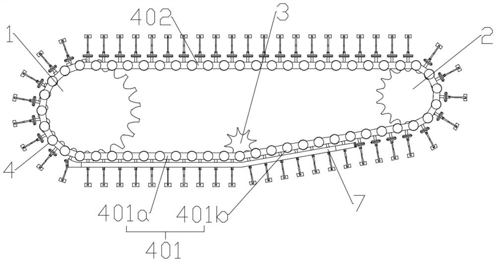
[0033] Such as figure 1 As shown, a fabric tensioning mechanism I is disclosed in this embodiment, which is used to tension the width direction of the fabric II, such as Figure 2-4 As shown, it includes a first sprocket set 1, a second sprocket set 2, a guide sprocket set 3, a chain 4 and a chain plate 5, and the first sprocket set 1 and the second sprocket set 2 are arranged at intervals, The chain 4 is closed around the first sprocket set 1 and the second sprocket set 2; the chain 4 includes a first chain part 401 and a second chain part 402, and the first chain part 401 is located on the side close to the fabric , the second chain part 402 is located on the side away from the cloth, and the guide sprocket set 3 is located on the first chain part 401; the first chain part 401 includes a cloth pressing part 401a401a and a cloth tensioning part 401b, the The guide sprocket group 3 is located at the connection position between the cloth pressing part 401a and the cloth tensio...


PUM


Abstract

The invention relates to a cloth tensioning mechanism, which comprises a first sprocket set, a second sprocket set, a guide sprocket set, a chain and a chain plate, the first sprocket set and the second sprocket set are arranged at intervals, The chain is closed around the first sprocket set and the second sprocket set; the chain includes a first chain part and a second chain part, and the guide sprocket set is located at the first chain part; the first chain part It includes a cloth pressing part and a cloth tensioning part, the guide sprocket set is located at the connection position between the cloth pressing part and the cloth tensioning part; the chains include at least two, the chain plates are located between the chains, and the Both ends of the chain plate are respectively fixedly connected with a chain, and a clamping assembly is arranged on the chain plate. The mechanism can realize tensioning in the width direction of the cloth, solves the problem that the existing technology cannot continuously stretch the width direction of the cloth during the traveling process of the cloth, improves the tensioning efficiency, and improves the quality of the cloth.

Description

technical field [0001] The invention belongs to the technical field of cloth production equipment, and relates to a cloth tensioning mechanism. Background technique [0002] my country's textile industry has generally adopted automated textile machinery. The fabric is stretched by the tensioning mechanism and then cut by the cloth cutting machine. The cut fabric must be smooth and coherent to ensure the quality of the product after the remaining processes. The tensioning mechanism of the existing cutting machine only realizes the tensioning of the cloth through the tensioning assembly composed of the cylinder and the roller body. In the fabric production process, it is generally guided to another step or rolled up by pulling. When pulling, the existing technology mostly uses stretching in the length direction of the fabric. Since the fabric itself is criss-crossed Weaving, therefore, during the pulling process, the length direction of the cloth pulling will be relatively el...

Claims


Application Information

Patent Timeline
Patent Type & Authority Patents(China)
IPC IPC(8): D06C3/02
CPCD06C3/02D06C3/025D06C3/023
Inventor 曾志敏陈淑敏
Owner 清远市诚鸿纺织有限公司
Why Eureka
Try Eureka