A method for quickly tightening the screen and preventing the screen from falling, and a vibrating screen

A vibrating sieve and sieve technology, which is applied to chemical instruments and methods, sieves, solid separation, etc., can solve the problems of large impact on production and no good solution, and achieve good vibration transmission effect

Inactive Publication Date: 2016-05-18
重庆恒伟林汽车零部件有限公司
View PDF6 Cites 0 Cited by
  • Summary
  • Abstract
  • Description
  • Claims
  • Application Information

AI Technical Summary

Problems solved by technology

The longer it takes to replace the screen, the greater the impact on production
[0008] In the industry, there has been no good solution for quick tensioning of the screen and secondary tensioning of the screen

Method used


Image

  • A method for quickly tightening the screen and preventing the screen from falling, and a vibrating screen
  • A method for quickly tightening the screen and preventing the screen from falling, and a vibrating screen
  • A method for quickly tightening the screen and preventing the screen from falling, and a vibrating screen

Examples


Embodiment 1

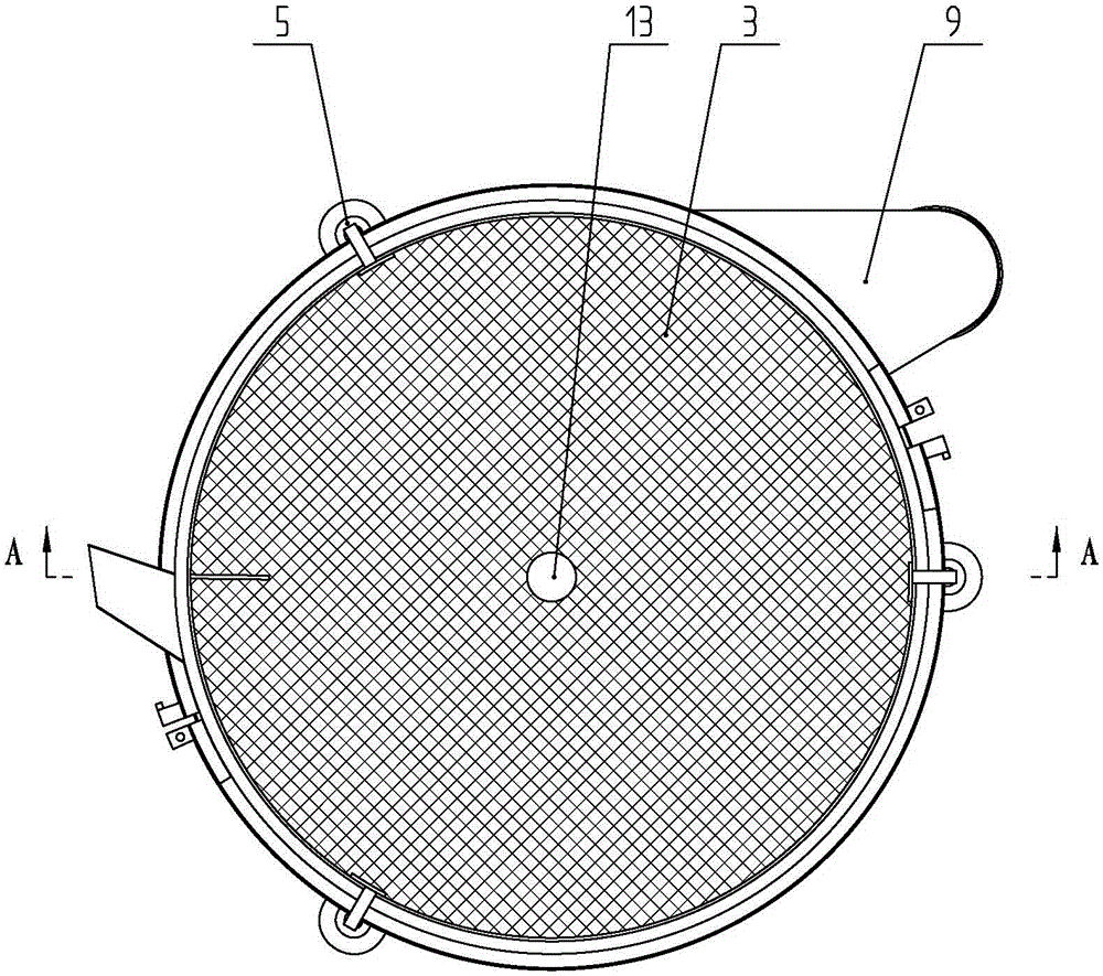
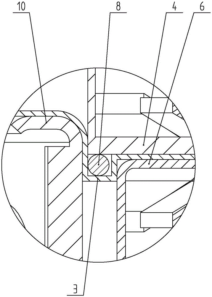
[0033] Such as Figures 1 to 3 As shown, the main part of the vibrating screen includes an upper screen frame 1, a lower screen frame 2, a screen 3, a press ring 8 and a tension ring 10. The tension ring 10 is arranged below the screen cloth 3 , and the press ring 8 is fixedly arranged at the bottom of the lower screen frame 2 . The connection between the upper and lower screen frames is provided with a flange structure. The specific connection method is that the lower end of the upper screen frame 1 is provided with a second flange 6, and the upper end of the lower screen frame 2 is provided with a first flange 4, a second flange 6 and The first flanges 4 are aligned, and the outer diameter of the upper screen frame 1 is smaller than the inner diameter of the lower screen frame 2 . The central position of the bottom surface of the lower screen frame 2 protrudes upwards to form a trapezoidal round platform 2.1, and the discharge port 9 is opened at the bottom of the lower scr...

Embodiment 2

[0044] Such as Figure 5 , 6 As shown, the difference from Embodiment 1 is that the lifter in this embodiment is a jack 14 . Jack 14 comprises base 14.1, two lower arms 14.2, two upper arms 14.3, leading screw 14.4, bearing pin 14.5 and bearing platform 14.6. The base 14.1 is fixed on the outer wall of the lower screen frame, and the carrying platform 14.6 is connected with one end of the top tight block. The upper end of upper arm 14.3 is all hinged on the bearing platform 14.6, the lower end of lower arm 14.2 is all hinged on the base 14.1; the lower end of upper arm 14.3 and the upper end of lower arm 14.2 are all hinged on pin 14.5. Leading screw 14.4 passes bearing pin 14.5 by thread fit mode; The upper end of each upper arm 14.3 and the lower end of each lower arm 14.2 all have the fan-shaped teeth that mesh with each other. When tightening the screen, turn the lead screw 14.4, and the distance between the two pin shafts 14.5 will decrease under the action of thread f...


PUM


Abstract

The invention relates to a method for quickly tightening screen cloth and preventing the screen cloth from falling. Screen frames and the screen cloth are adopted in the method. The method is characterized by comprising the following steps that firstly, the screen cloth is laid flat on the upper end face of the lower screen frame; afterwards, the screen cloth is connected with the top of a central supporting column; next, the upper screen frame is vertically placed down, the edge of the screen cloth is bent downwards through a cloth pressing ring on the upper screen frame, and then the edge of the screen cloth is laid flat between an upper screen frame flange and a lower screen frame flange; after that, the upper screen frame flange and the lower screen frame flange are fastened into a whole through a V-shaped lacing ring; finally, a lifting jack is controlled to drive a tightening ring to move upwards to abut against the screen cloth, so that the screen cloth is installed and tightened. The method has the advantages that the cloth pressing ring is fixedly arranged at the lower portion of the upper screen frame, the edge of the screen cloth is bent downwards and then bent upwards through the cloth pressing ring, and therefore the effect of further tightening the screen cloth can be achieved; besides, the edge of the screen cloth is not prone to looseness through two times of reverse bending.

Description

technical field [0001] The invention belongs to the technical field of material screening, and in particular relates to a vibrating screen. Background technique [0002] Enterprises widely use vibrating screens to sort materials. Commonly used vibrating screens include structural components such as upper screen frame, lower screen frame, grid frame, screen mesh, spring connected to the screen frame, vibration motor, etc. The screen is vibrated by starting the vibrating motor, so that the small particles pass through the screen and leak down, and the large particles are blocked on the screen. The screen used in the vibrating screen is generally woven with metal wire, nylon wire, etc. The process of tightening the screen mesh in the prior art is as follows: [0003] (1) Apply a new square screen on the grid, flatten the screen and bend it, so that the screen is bent and pasted on the outer wall of the grid; [0004] (2) Tighten the lower screen with the pressure ring first...

Claims


Application Information

Patent Timeline
Patent Type & Authority Patents(China)
IPC IPC(8): B07B1/28B07B1/46
CPCB07B1/46B07B1/48
Inventor 任祥生
Owner 重庆恒伟林汽车零部件有限公司
Why Eureka
Try Eureka