Vehicle body structure

A body, front and rear technology of the body, applied to the upper structure, upper structure sub-assembly, vehicle parts, etc., can solve the problems of difficult design of the body, deformation, etc., and achieve the effect of efficient absorption

Active Publication Date: 2017-08-29
HONDA MOTOR CO LTD
View PDF9 Cites 6 Cited by
  • Summary
  • Abstract
  • Description
  • Claims
  • Application Information

AI Technical Summary

Problems solved by technology

However, in such a vehicle body structure, the vibration of the floor can be suppressed by adding a cross member for connecting the underframe and the side members, but the body will def

Method used


Image

  • Vehicle body structure
  • Vehicle body structure
  • Vehicle body structure

Examples


Embodiment Construction

[0037] One embodiment of the present invention will be described below based on the drawings.

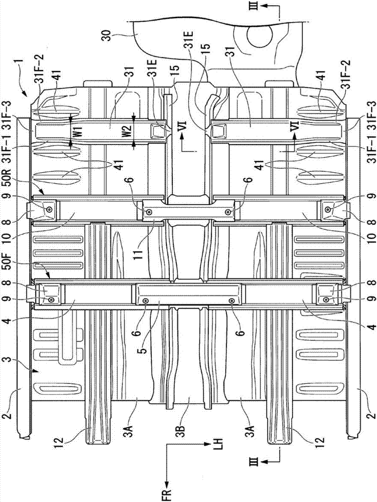
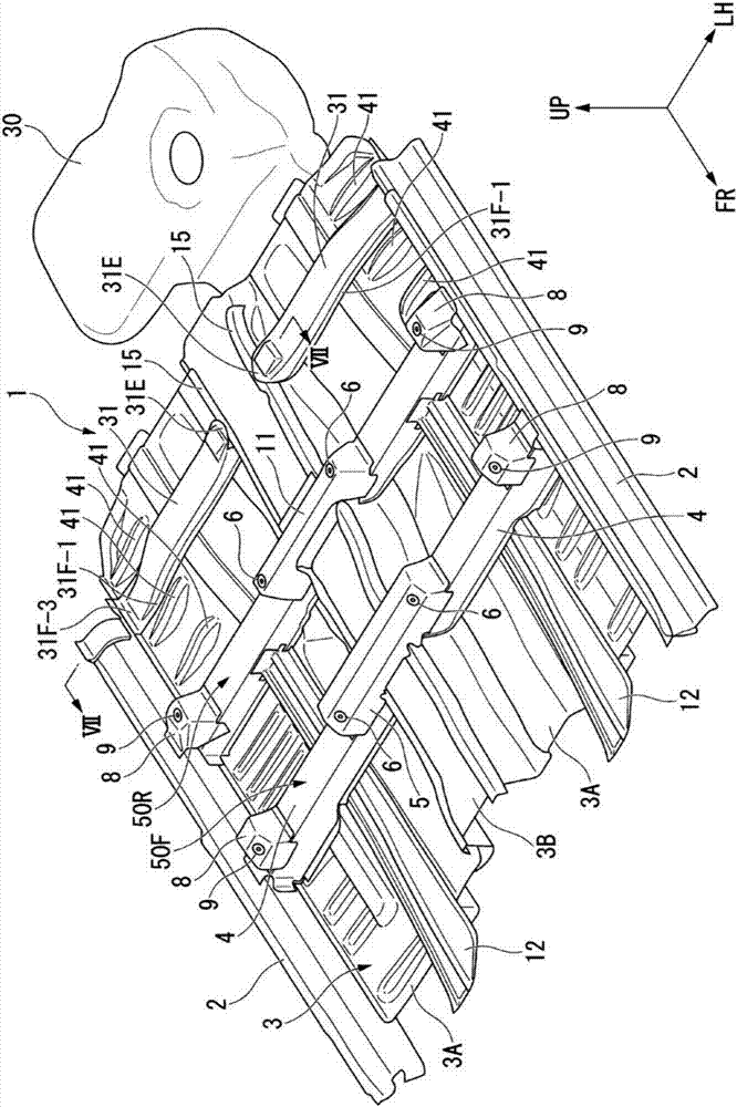
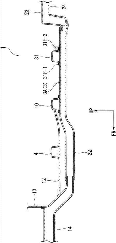
[0038] figure 1 is a diagram of the frame portion under the cabin of the vehicle 1 according to the present embodiment seen from above, figure 2 It is a diagram of the same skeleton viewed from the upper left front. in addition, image 3 is along figure 1 A diagram of the section of the line III-III, Figure 4 is a diagram of the skeleton part seen from below.

[0039] In the vehicle 1 according to the present embodiment, side members 2 extending substantially in the vehicle front-rear direction are disposed below the left and right side portions of the vehicle. Left and right end portions of a floor panel 3 below the vehicle compartment are joined to inner surfaces in the vehicle width direction of the left and right side members 2 .

[0040] The floor 3 has floor portions 3A on the left and right in the vehicle width direction, and a tunnel portion 3B substantially in the c...


PUM


Abstract

The invention provides a vehicle body structure. The vehicle body structure has a cross beam extending substantially along a vehicle width direction on an upper surface of a floor part and used for connecting a channel part and side beams and reinforcing floor. A jointing part with the cross beam in an area of the floor part between a chassis outer a carriage and the side beams has an angle changing part which is bent or curved in a concave shape towards a lower side with an angle towards an outer side of a vehicle body direction changing. The cross beam is formed in such a shape that the cross section width in a front-back direction in the area between the chassis outside the carriage and the side beams is narrower than the cross section width in the front-back direction in an area between the channel part and the chassis outside the carriage, and in addition, the cross section height of the area between the chassis outside the carriage and the side beams gradually decreases towards the side beam sides. Thus, when imposed with an impact load from a vehicle body side, the vehicle body structure can maintain very high energy absorption performance, and can inhibit vibration of floor during normal traveling of a vehicle.

Description

technical field [0001] The invention relates to a vehicle body structure under a compartment. Background technique [0002] In the prior art, there is known a vehicle body structure in which an underframe extending approximately in the front-rear direction of the vehicle body is disposed below the floor, and the underframe is connected to side members ( Refer to Patent Document 1). [0003] [Prior Art Literature] [0004] 【Patent Literature】 [0005] Patent Document 1: Japanese Invention Patent Laid-Open Publication No. 2013-99997 [0006] In the vehicle body structure disclosed in Patent Document 1, since the underframe supporting the lower surface of the floor is joined to the side beams via the beams, the rigidity of the floor can be kept high and vibration of the floor during normal running of the vehicle can be suppressed. However, in such a vehicle body structure, the vibration of the floor can be suppressed by adding a cross member for connecting the underframe an...

Claims


Application Information

Patent Timeline
IPC IPC(8): B62D25/20
CPCB62D25/20
Inventor 藤沢耕太梅原康平
Owner HONDA MOTOR CO LTD
Why Eureka
Try Eureka