
Flexible connection member and robot foot structure using same
A technology of flexible connectors and robots, which is applied in the field of robots and can solve problems such as robots turning over
Patent Information
- Authority / Receiving Office
- CN · China
- Patent Type
- Applications(China)
- Current Assignee / Owner
- Publication Date
- 2017-08-29
Smart Images
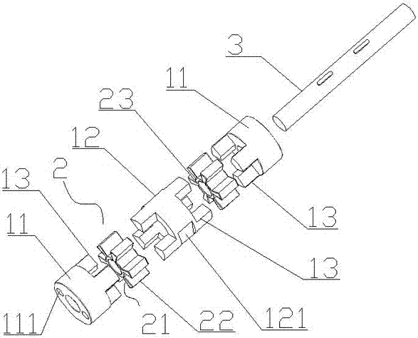
Figure 1 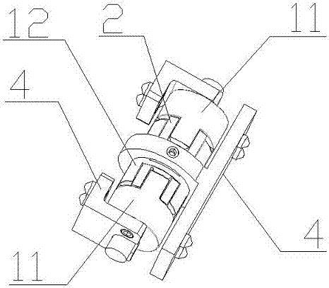
Figure 2 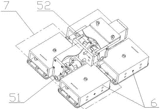
Figure 3
Abstract
Description
technical field
[0001] The invention relates to the field of robots, in particular to a flexible connector and a robot foot structure using the connector. Background technique
[0002] Biped robot is a new type of robot that can imitate human walking. Similar to the human walking trajectory, the biped robot walking trajectory consists of discrete points, so it can also adapt to various types of ground in theory. Biped robots have the same physical structure as humans, and are suitable for working in various environments designed for humans. They have partially replaced humans in factories and can participate in dangerous tasks such as fire fighting, disaster relief, and flood fighting. Biped robot has become one of the most representative topics in the field of intelligent robot research.
[0003] Attitude maintenance during biped robot walking is a major difficulty in biped robot research. When the soles of the biped robot land on the ground, if the soles of the feet are...
Examples
Embodiment
[0027] Such as figure 1 As shown, a flexible connector includes an intermediate shaft 3 and at least three rigid joints, a fixed joint 2 made of rubber is arranged between every two rigid joints, and the intermediate shaft 3 passes through the The rigid joint and the fixed joint 2 are keyed to the fixed joint 2; the fixed joint 2 includes a sleeve 23 and annular blades 22 uniformly distributed outside the sleeve 23, and a connection space is formed between every two blades 22 21. The one end of the rigid joint in contact with the fixed joint 2 is evenly distributed with bosses 13 corresponding to the shape of the connection space 21, and the bosses 13 on two adjacent rigid joints are alternately inserted into the adjacent connection spaces 21 The rigid joint includes two end joints 11 and at least one intermediate joint 12, the end joint 11 is provided with a connection hole 111 away from the end of the boss 13, and the outer surface of the intermediate joint 12 is provided wi...