
Stop valve device and fluid conveying device

A shut-off valve and fluid technology, which is applied in mechanical equipment, parts of pumping devices for elastic fluids, liquid variable capacity machinery, etc., can solve problems such as difficult medium transportation and insufficient extrusion

Active Publication Date: 2017-08-29
珠海优特智厨科技有限公司
View PDF5 Cites 0 Cited by
  • Summary
  • Abstract
  • Description
  • Claims
  • Application Information

AI Technical Summary

Problems solved by technology

[0004] Based on this, it is necessary to provide a shut-off valve device that can reduce the wear of the conveying device and improve the conveying efficiency in view of the problems of the conveying device caused by the existing pump body sliding through the conveying device, such as the wear of the conveying device, the extrusion is not in place, and the medium is difficult to convey.

Method used


Image

  • Stop valve device and fluid conveying device
  • Stop valve device and fluid conveying device
  • Stop valve device and fluid conveying device

Examples


Embodiment Construction

[0029] In order to make the purpose, technical solution and technical effect of the present invention clearer, specific embodiments of the present invention will be described below in conjunction with the accompanying drawings. It should be understood that the specific embodiments described here are only used to explain the present invention, not to limit the present invention.

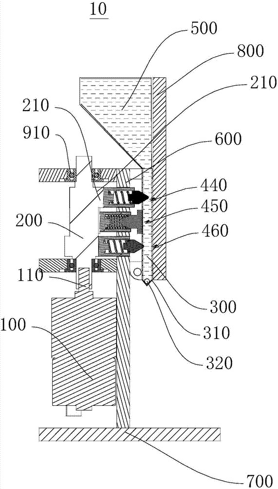
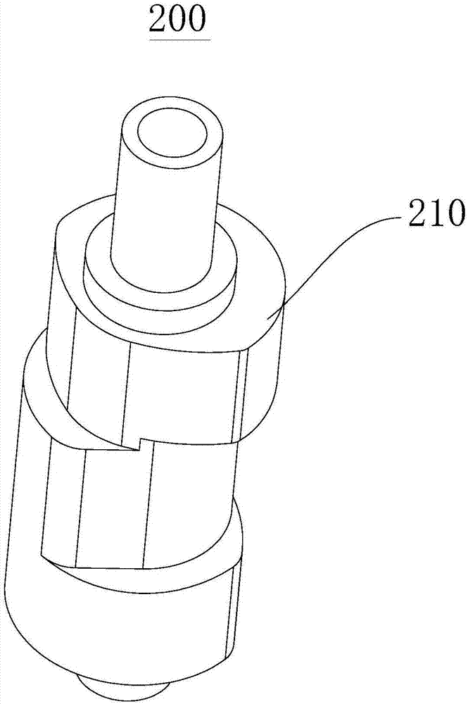
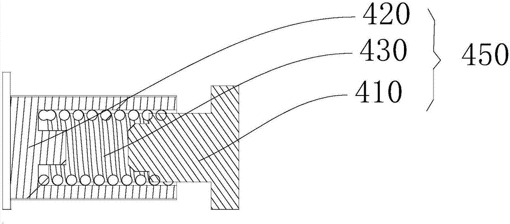
[0030] See figure 1 , the embodiment of the present invention provides a stop valve device 10 . The stop valve device 10 includes a drive shaft 200 . The driving shaft 200 includes a plurality of eccentric members 210 arranged along the extending direction of the driving shaft 200 . The plurality of eccentric members 210 are arranged alternately in the circumferential direction of the drive shaft 200 . The cut-off valve device 10 further includes a transport pipe 300 , and the transport pipe 300 is spaced and opposite to the drive shaft 200 . The stop valve device 10 also includes an inlet extrusi...


PUM


Abstract

The invention discloses a stop valve device and a fluid conveying device. The stop valve device comprises a driving shaft and a conveying pipe; eccentric components arranged along the extension direction of the driving shaft are arranged in the circumferential direction of the driving shaft in a staggered mode; an inlet extrusion assembly, one or more middle extrusion assemblies and an outlet extrusion assembly are arranged in sequence in the extension direction of the conveying pipe; the outlet extrusion assembly extrudes and intercepts fluid in the conveying pipe, and the inlet extrusion assembly and the middle extrusion assemblies leave the conveying pipe; the inlet extrusion assembly extrudes and intercepts the fluid in the conveying pipe, the outlet extrusion assembly leaves the conveying pipe, and the middle extrusion assemblies extrude the conveying pipe; then the middle extrusion assemblies and the inlet extrusion assembly leave the conveying pipe; and the process is repeated to enable the fluid in the conveying pipe to quickly flow downstream. According to the stop valve device and the fluid conveying device, due to the fact that the extruding assemblies extrude the conveying device vertically, friction to the conveying device does not exist, and therefore the abrasion to the conveying device can be reduced, and meanwhile, the good extrusion effect can be achieved.

Description

technical field [0001] The invention relates to the field of pump body transportation, in particular to a shut-off valve device and fluid conveying equipment. Background technique [0002] Traditional quantitative taking devices for edible liquid seasonings usually supply liquid seasonings through integral airtight pipelines. The liquid condiment in the pipeline of the quantitative taking device can flow into the receiving cup under the action of the pressure difference inside and outside the pipeline. [0003] Traditional edible liquid condiment quantitative taking devices usually use a pump body to transport liquid condiment. Specifically, a circular extruding assembly is arranged on the pump head. The circular extrusion assembly rotates as a whole around a fixed axis. The circular extruding assembly rotates to a position close to the delivery tube and then continues to rotate, and slides along the radial direction of the delivery tube and squeezes the delivery tube. Th...

Claims


Application Information

Patent Timeline
IPC IPC(8): F04B15/02F04B53/00
CPCF04B15/02F04B53/00
Inventor 王政军张捷挺肖强程伟刘军超詹大强
Owner 珠海优特智厨科技有限公司
Learn More