Dropper fatigue testing machine

A technology for fatigue testing machines and force-applying components, applied in the testing of mechanical components, testing of machine/structural components, measuring devices, etc.

Active Publication Date: 2017-08-29
JINAN KEHUI TESTING INSTR
View PDF8 Cites 21 Cited by
  • Summary
  • Abstract
  • Description
  • Claims
  • Application Information

AI Technical Summary

Problems solved by technology

[0011] 1. How to realize the high-frequency fatigue test of the hanging string under the amplitude of 200mm;

Method used


Image

  • Dropper fatigue testing machine
  • Dropper fatigue testing machine
  • Dropper fatigue testing machine

Examples


Embodiment Construction

[0033] The features and principles of the present invention will be described in detail below in conjunction with the accompanying drawings, and the examples given are only used to explain the present invention, not to limit the protection scope of the present invention.

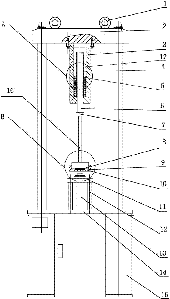
[0034] Such as figure 1 As shown, the invention includes an upper support, a lower support, a force applying part, a force buffering part and a sensor. Wherein the upper support member includes an upper beam 2 and a suspension ring 1, and the suspension ring 1 is fixedly arranged on the top surface of the upper beam 2, and the suspension ring can be suspended and fixed during use. The lower supporting member includes a base 15 , and the force applying component is fixed on the working surface 14 of the base 15 . Fasten together with four columns to form a rigid frame between the upper beam 2 and the work table surface 14, and for preventing vibration, the base 15 is welded by thick steel plates.

[0035] T...


PUM


Abstract

A dropper fatigue testing machine comprises an upper strutting piece, a lower strutting piece, a force application part, a force buffer part and a sensor. The force application part is arranged on the lower strutting piece, the force application part is arranged on the upper strutting piece, the sensor is fixedly arranged on a pulling force buffer part, a dropper sample is arranged between the force application part and the force buffer part, the bottom end of the dropper sample is in contact connection with the top portion of the force application part, and the top end of the dropper sample is fixedly connected with the bottom portion of the force buffer part. A high-speed electric cylinder performs loading and unloading of the dropper sample from down to up, and the speeds and the displacements of the loading and the unloading in each phase can be controlled through a pretext computer program. The completion of the compression in half sine wave and the buffer inertia force of the dropper sample in the declining process are realized. The dropper sample is clamped to simulate the forced state of the dropper in a carrier cable, a spring is employed to replace the carrier cable, a buffer spring is located at a vertical position, the upper end of the buffer spring is fixed, the lower end of the buffer spring is floated, and the buffer spring is effected on the inertia force on the dropper sample.

Description

technical field [0001] The invention relates to the technical field of hanging string fatigue testing equipment, in particular to a hanging string fatigue testing machine. Background technique [0002] Catenary suspension string fatigue test is used to simulate the service life of the suspension string between the catenary cable and the catenary wire in the state of frequent "supporting" of the pantograph. Among them, the catenary is a high-voltage transmission line erected in a "zigzag" shape along the sky above the rails in the electrified railway for the pantograph to take current. The catenary is the main frame of the railway electrification project, and it is a special form of transmission line erected along the railway line to supply power to the electric locomotive. It is composed of contact suspension, supporting device, positioning device, pillar and foundation. The catenary mainly includes the following items: basic components, such as cement pillars, steel colum...

Claims


Application Information

Patent Timeline
Patent Type & Authority Applications(China)
IPC IPC(8): G01M13/00
CPCG01M13/00Y02E30/30
Inventor 郑全山
Owner JINAN KEHUI TESTING INSTR
Why Eureka
Try Eureka