
LED lamp strip, backlight module and display device

A technology of LED light strips and light guide plates, applied in optics, nonlinear optics, instruments, etc., can solve problems such as affecting optical effects, reducing width, and failing to meet requirements, and achieves the effect of meeting the needs of narrow borders and reducing width

Active Publication Date: 2017-08-29
XIAMEN TIANMA MICRO ELECTRONICS
View PDF6 Cites 5 Cited by
  • Summary
  • Abstract
  • Description
  • Claims
  • Application Information

AI Technical Summary

Problems solved by technology

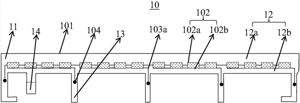
[0003] As the core component of the backlight module, the LED light bar is particularly important. Among them, when the LED light bar adopts double-layer wiring, the width is smaller than when using single-layer wiring, which is more in line with the needs of narrow frame. However, the LED light When the strip adopts double-layer wiring, it is necessary to set a via hole to electrically connect the double-layer wiring. The existence of the via hole will limit the further reduction of its width, especially the width of the light strip corresponding to the tail of the LED, because the conduction There will be some protrusions in the hole. If the via hole is placed on the light output side of the LED, the optical effect will be affected. Therefore, the via hole can only be placed on the side of the LED tail. In the current design, the width of the light bar corresponding to the LED tail is only It can be about 0.8-0.9mm, which cannot meet the requirements of current narrow-frame display devices

Method used


Image

  • LED lamp strip, backlight module and display device
  • LED lamp strip, backlight module and display device
  • LED lamp strip, backlight module and display device

Examples


Embodiment Construction

[0023] The present invention will be further described in detail below in conjunction with the accompanying drawings and embodiments. It should be understood that the specific embodiments described here are only used to explain the present invention, but not to limit the present invention. In addition, it should be noted that, for the convenience of description, only some structures related to the present invention are shown in the drawings but not all structures.

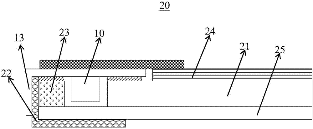
[0024] The invention provides an LED light bar, which includes: a plurality of LEDs and a flexible circuit board. Wherein, the flexible circuit board includes a substrate and a first wiring and a second wiring respectively located on both sides of the substrate. The substrate includes a main body and a branch extending from the main body. The first wiring and the second wiring pass through The via hole on the branch part is electrically connected, so that the via hole limiting the width of the LED light bar is mov...


PUM


Abstract

The invention provides an LED lamp strip which comprises multiple LEDs and a flexible circuit board. The flexible circuit board comprises a base board, a first wire and a second wire, wherein the first wire and the second wire are located on two sides of the base board respectively, the base board comprises a body portion and branch portions extending out from the body portion, the first wire and the second wire are electrically connected through via holes located in the branch portions, so that remarkable decrease of the width of the LED lamp strip is achieved by limiting downward movement of via holes of LED lamp strip in the width direction towards the branch portions, and the narrow-frame demand of a display device is met.

Description

technical field [0001] The invention relates to the field of display technology, and in particular to an LED light bar, a backlight module comprising the LED light bar, and a display device. Background technique [0002] The display devices currently on the market are mainly backlight liquid crystal display devices, which include a casing, a liquid crystal panel disposed in the casing, and a backlight module. Since the liquid crystal panel itself does not emit light, it needs a light source provided by the backlight module to display images normally. , therefore, the backlight module is one of the key components of the display device. Backlight modules are divided into side-type backlight modules and direct-type backlight modules according to the location of the light source. Among them, the side-type backlight module is to install the LED light bar at the edge of the backlight module behind the liquid crystal panel. Compared with the direct-type backlight module, the side-...

Claims


Application Information

Patent Timeline
IPC IPC(8): G02F1/13357
CPCG02F1/133615
Inventor 张豪尔
Owner XIAMEN TIANMA MICRO ELECTRONICS
Learn More