Anonymous voting system for meeting voting
A conference and voting device technology, applied in the field of voting system, can solve the problems of not choosing one's own true thoughts and differences, achieve high accuracy and avoid misoperation
- Summary
- Abstract
- Description
- Claims
- Application Information
AI Technical Summary
Problems solved by technology
Method used
Image
Examples
Embodiment 1
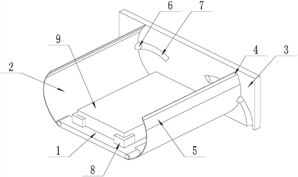
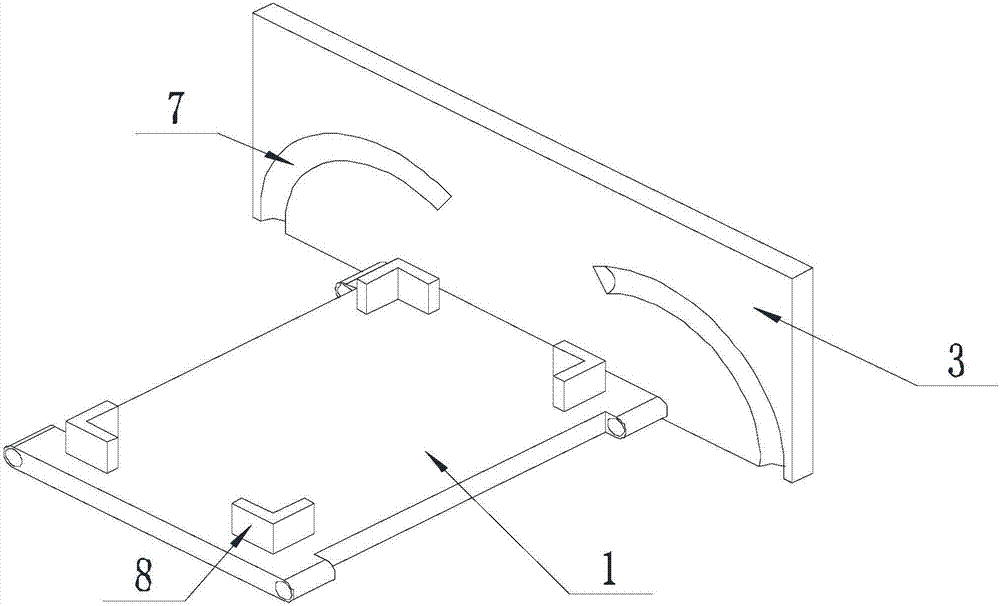
[0031] Such as Figure 1-Figure 4 As shown, the anonymous voting system for conference voting of the present invention includes a mounting board 1 and a voting device 9 connected to a controller, and the controller displays the statistics of the information delivered by the voting device 9 on the display screen, and the voting device 9 is located on the upper surface of the mounting plate 1, and both ends of the mounting plate 1 are hingedly provided with a shutter 2, and the shutter 2 rotates around the hinge axis to cover the voting device 9 located on the mounting plate 1;
[0032] A baffle 3 is arranged on the side of the mounting plate 1 perpendicular to the hinge axis.
[0033] When anonymous voting is required, first rotate the shielding plate 2, and contact the ends of the shielding plate 2 away from the mounting plate 1 with each other, so that the shielding plate 2 covers the voting device 9, and then move the hand away from the mounting plate 1 from the end of the s...
Embodiment 2
[0035] The present invention is based on embodiment 1, and the present invention is further described.
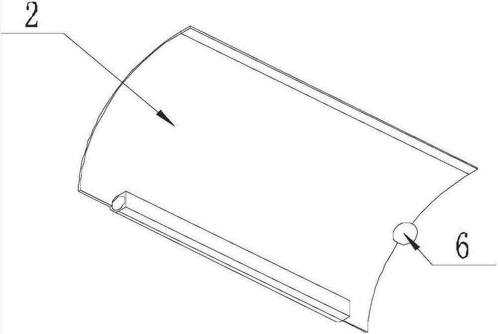
[0036] Such as Figure 1-Figure 4 As shown in the anonymous voting system for meeting voting in the present invention, the shutter 2 is bent into an arc-shaped plate, and its inner concave surface faces the voting device 9, and the shutter 2 rotates around the hinge axis, and the shutter 2 is away from the hinge axis. When one ends of the louvers are in contact with each other, the shutters 2 are coaxial with each other.
[0037] Further, magnets 4 are provided at the mutual contact ends of the shutters 2 , and the ends of the shutters 2 away from the hinge axis are attracted and fixed to each other by the magnets 4 .
[0038] Further, a perspective part 5 is provided on the side wall of the shield 2 away from the hinge axis, and when the ends of the shield 2 away from the hinge axis are in contact with each other, the voting device 9 can be seen through the see-through pa...
Embodiment 3
[0041] The present invention is based on embodiment 1, and the present invention is further described.
[0042] Such as Figure 1-Figure 4 As shown, in the anonymous voting system for conference voting of the present invention, a guide block 6 is provided on the end of the shutter 2 close to the shutter 3, and a guide groove 7 is provided on the surface of the shutter 3 near the shutter 2, so The guide groove 7 is bent into an arc shape, and there are two guide grooves 7, which are symmetrically arranged on the baffle plate 3 along the center line of the baffle plate 3 perpendicular to the horizontal plane;
[0043] The guide blocks 6 are respectively matched with a guide groove 7, and the bending axis of the guide groove 7 is collinear with the hinge axis of the shroud 2 where the guide block 6 matched with it is located. When the hinge axis rotates, the guide block 6 slides in the guide groove 7 .
[0044] Further, the guide block 6 is spherical, and the cross section of t...
PUM
 Abstract
Description
Claims
Application Information
 - R&D
- Intellectual Property
- Life Sciences
- Materials
- Tech Scout
- Unparalleled Data Quality
- Higher Quality Content
- 60% Fewer Hallucinations
Browse by: Latest US Patents, China's latest patents, Technical Efficacy Thesaurus, Application Domain, Technology Topic, Popular Technical Reports.
© 2025 PatSnap. All rights reserved.Legal|Privacy policy|Modern Slavery Act Transparency Statement|Sitemap|About US| Contact US: help@patsnap.com


