
Filter device, hydraulic system and backwashing method

一种过滤设备、反冲洗的技术,应用在化学仪器和方法、过滤分离、膜过滤器等方向,能够解决颗粒污物阻塞、过滤设备性能不利影响、有效过滤元件面积的大小不能明显减小等问题,达到节约空间、长使用寿命的效果

Active Publication Date: 2017-08-29
HYDAC PROCESS TECH
View PDF3 Cites 3 Cited by
  • Summary
  • Abstract
  • Description
  • Claims
  • Application Information

AI Technical Summary

Problems solved by technology

A significantly more compact construction is required for this, but the size of the effective filter element area used in this case cannot be significantly reduced, because otherwise particulate contamination of the fluid to be filtered would quickly cause clogging and premature replacement of the new filter elements. The filter element replaces the old filter element, which adversely affects the performance of the filter equipment

Method used


Image

  • Filter device, hydraulic system and backwashing method
  • Filter device, hydraulic system and backwashing method
  • Filter device, hydraulic system and backwashing method

Examples


Embodiment Construction

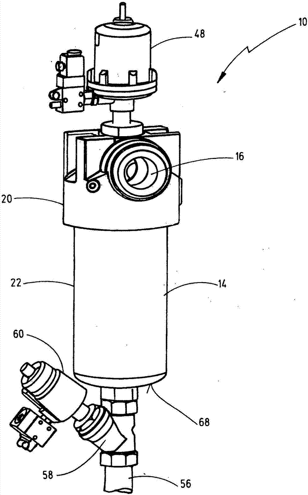
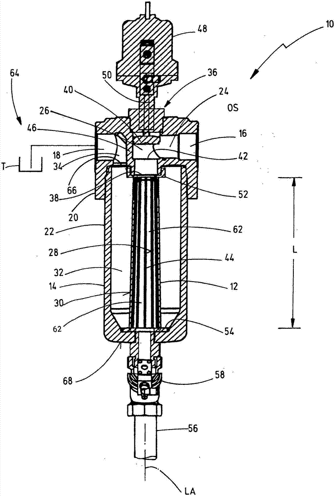
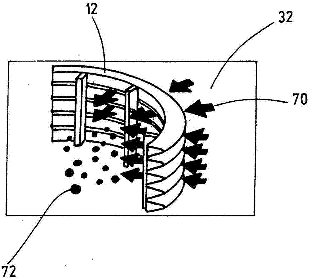
[0033] exist figure 1 and 2 shows a filter device 10 according to the invention, which has a filter element 12 . The filter element 12 is accommodated in a filter housing 14 which has fluid connections 16 , 18 for the raw liquid or filtrate. The fluid connections 16 , 18 are connected to one another via the filter element 12 in a fluid-conducting manner. The filter housing 14 includes a head part 20 and a pot-shaped receiving part 22 . In this case, the head piece 20 has fluid connections 16 , 18 for unfiltrate and filtrate. The unfiltrate is guided from the fluid connection 16 for the unfiltrate along a first fluid-conducting path 24 in the direction of the interior of the filter element 12 . In this case, the first fluid-conducting path 24 runs at right angles to the deflection 26 . During filter operation, the fluid then flows through the filter element 12 from the inside to the outside, with dirt, in particular particles, accumulating on the inner side 28 of the filte...


PUM


Abstract

The invention relates to a filter device (10) comprising a filter element (12) which is accommodated in a filter housing (14) with fluid connection points (16, 18) for the non-filtrate and filtrate and said element can be passed through in both directions for filtrating the non-filtrate or for back washing for cleaning particle contaminations (72), said filter device also comprises a pressure control device (36) which generates a post-suctioning effect in order to improve the cleaning of the particle contaminations (72) on the backwashing filter element (12). Said filter element is characterized in that said filter device (10) is designed as a one filter-element solution and that, in a predetermined exchange, said single filter element (12) for filtering can be used for backwashing or can be backwashed using the pressure control device (36). The invention also relates to a hydraulic system (64) and to a method for backwashing a filter element (12) of a filter device (10) of said type.

Description

technical field [0001] The invention relates to a filter device having a filter element accommodated in a filter housing having fluid connections for unfiltrate and filtrate, and the filter element For filtering the non-filtrate or for backwashing in order to remove particulate dirt, a flow through in both directions is possible, and the filter device has a pressure control device, by means of which a regeneration can be generated on the filter element to be backwashed. Suction effect for improved cleaning of particulate dirt. The invention also relates to a hydraulic system with such a filter device and a method for backflushing a filter element of such a filter device. Background technique [0002] Such filter devices are known in the prior art, for example from WO 2009 / 062644 A1. In such a filter device, a plurality of filter elements are arranged offset relative to one another on a partial circle, and a device is provided for backwashing a corresponding one of such fil...

Claims


Application Information

Patent Timeline
Patent Type & Authority Applications(China)
IPC IPC(8): B01D35/16B01D29/35B01D29/48B01D29/66B01D29/90
CPCB01D29/35B01D29/48B01D29/668B01D29/906B01D35/16B01D2201/02
Inventor M·奥尔朔克C·辛德勒S·拉比布
Owner HYDAC PROCESS TECH
Learn More