
Managed pressure drilling

a wellbore and pressure management technology, applied in the direction of drilling pipes, drilling well accessories, drilling holes/well accessories, etc., can solve the problems of loss of production fluid, well underbalance, undesirable blowout or “kick” of production fluid through the wellbore,

Inactive Publication Date: 2006-07-20
WEATHERFORD TECH HLDG LLC
View PDF77 Cites 122 Cited by
  • Summary
  • Abstract
  • Description
  • Claims
  • Application Information

AI Technical Summary

Benefits of technology

[0029] In a further aspect, embodiments of the present invention include a method of forming a wellbore, comprising inserting a tubular body into a wellbore formed in an earth formation; circulating a foamed cement through the tubular body and into an annulus between the outer diameter of the tubular body and the wellbore; and tailoring a density of the foamed cement along the annulus using one or more pressure control mechanisms.

Problems solved by technology

When Pf is greater than Pw, the well is underbalanced.
Underbalanced conditions within the wellbore facilitate production of fluid from the formation to the surface of the wellbore because the higher pressure fluid flows from the formation to the lower pressure area within the wellbore, but the underbalanced conditions may at the same time cause an undesirable blowout or “kick” of production fluid through the wellbore up to the surface of the wellbore.
Additionally, if the well is drilled in the underbalanced conditions, production fluids may rise to the surface during drilling, causing loss of production fluid.
When the reverse pressure relationship occurs such that Pw is greater than Pf, the well is overbalanced.
Overbalanced conditions within the wellbore are advantageous to control the well and prevent blowouts from occurring, but disadvantages often ensue when Pw becomes substantially greater than Pf.
Specifically, the drilling fluid used when drilling the wellbore may flow into the formation, causing loss of expensive drilling fluid as well as decrease in productivity of the formation.
Controlling Pw when the variable of drilling fluid is involved is difficult because of the nature of fluid flow within the wellbore.
The pressure differential between ECD within the wellbore and Pf at increasing depths can cause the wellbore to become overbalanced, inviting the problems described above in relation to substantially overbalanced wells.
The difference between ECD and Pf can be particularly problematic in extended reach wells, which are drilled to great lengths relative to their depths.
When drilling extended reach wells, placing more casing strings or casing sections of decreasing inner diameters within the wellbore at increasing depths causes the path for conveyance hydrocarbons and / or running tools within the wellbore to become very restricted.
Some deep wellbores are impossible to drill because of the number of casing sections or casing strings necessary to complete the well.
When using a valve to choke fluid flow at the surface during drilling, high wellhead pressure results.
High wellhead pressure exerted on a blowout preventer (“BOP”) increases strain on the equipment and could result in unsafe conditions due to lack of pressure barrier between the wellbore and the surface, possibly leading to shutdown of the operation at least for the time necessary to accomplish replacement of the BOP.
The largely unpredictable effects of these variables cause the wellbore pressure to constantly change, especially with increasing depth within the wellbore.
Because the drilling fluid downhole and its resulting pressure are difficult to predict, controlling the wellbore pressure downhole from the surface is not very exact.
An additional problem with controlling Pw when drilling results because of the increasing pressure of fluid with increasing depth, or the sloped pressure gradient.
Formation fluids within the interstitial spaces in the formation may not be adequately pressurized at one depth but too pressurized at another depth, so that the well is underbalanced at one depth and overbalanced at the other depth.
Controlling Pw with respect to Pf at one depth may not control Pw with respect to Pf at another depth because of the increasing pressure of fluid with increasing depth.
The attempts to control Pw from the surface of the wellbore do not address the dynamic nature of the wellbore at different depths, as formation fluids are not consistently pressurized at different depths of the wellbore.
Depending upon the depth of the wellbore, it can be impossible to maintain adequate wellbore pressure control throughout the wellbore without exceeding Pfrac under normal circumstances.
The use of foam is often problematic because the flow behavior of foam is almost impossible to accurately determine due to the expansion of foam as it travels up the annulus.
If the foam quality and other behavioral flow properties of the foam deviate outside of a given range, the cuttings-carrying ability of the foam is compromised and may result in insufficient removal of the cuttings from the wellbore.
Therefore, knowledge of the flow regime of the foam is effectively “lost” while the foam is traveling up through the annulus, in between the bottom of the wellbore and the surface of the wellbore, compromising effective cuttings removal.

Method used


Image

  • Managed pressure drilling
  • Managed pressure drilling
  • Managed pressure drilling

Examples


Embodiment Construction

[0053] Embodiments of the present invention allow control of fluid pressure throughout the wellbore using various pressure control devices and various drilling fluids. Further, embodiments of the present invention provide sufficient pressure control within the wellbore to allow maintaining a given pressure profile throughout the wellbore. Additionally, embodiments of the present invention provide a closed-loop fluid circulating system for drilling wells in which fluid flow properties may be controlled, tailored as desired, and maintained for fluid flowing into the wellbore, return fluid flowing out of the wellbore, and fluid flowing throughout the entire wellbore.

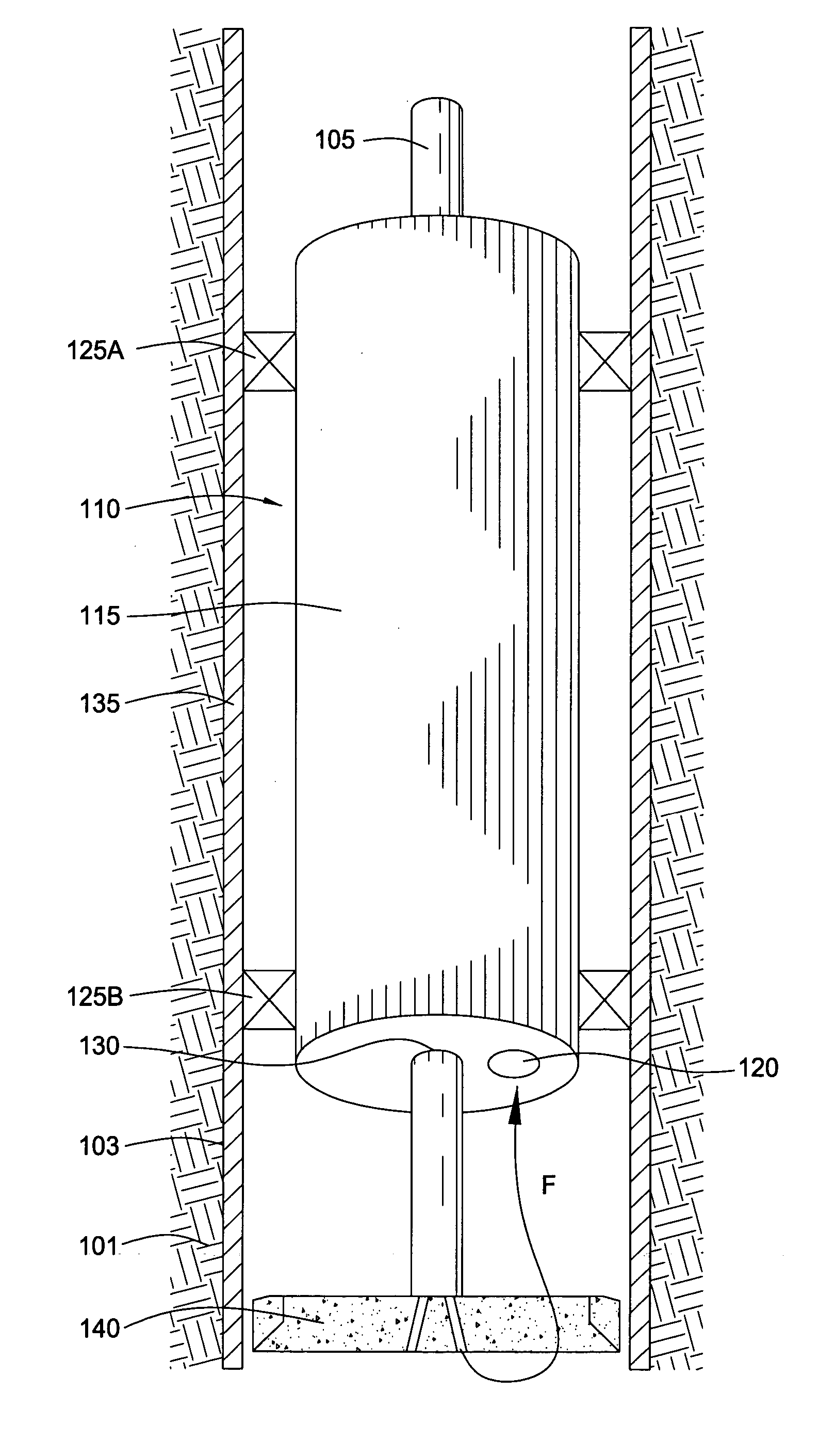
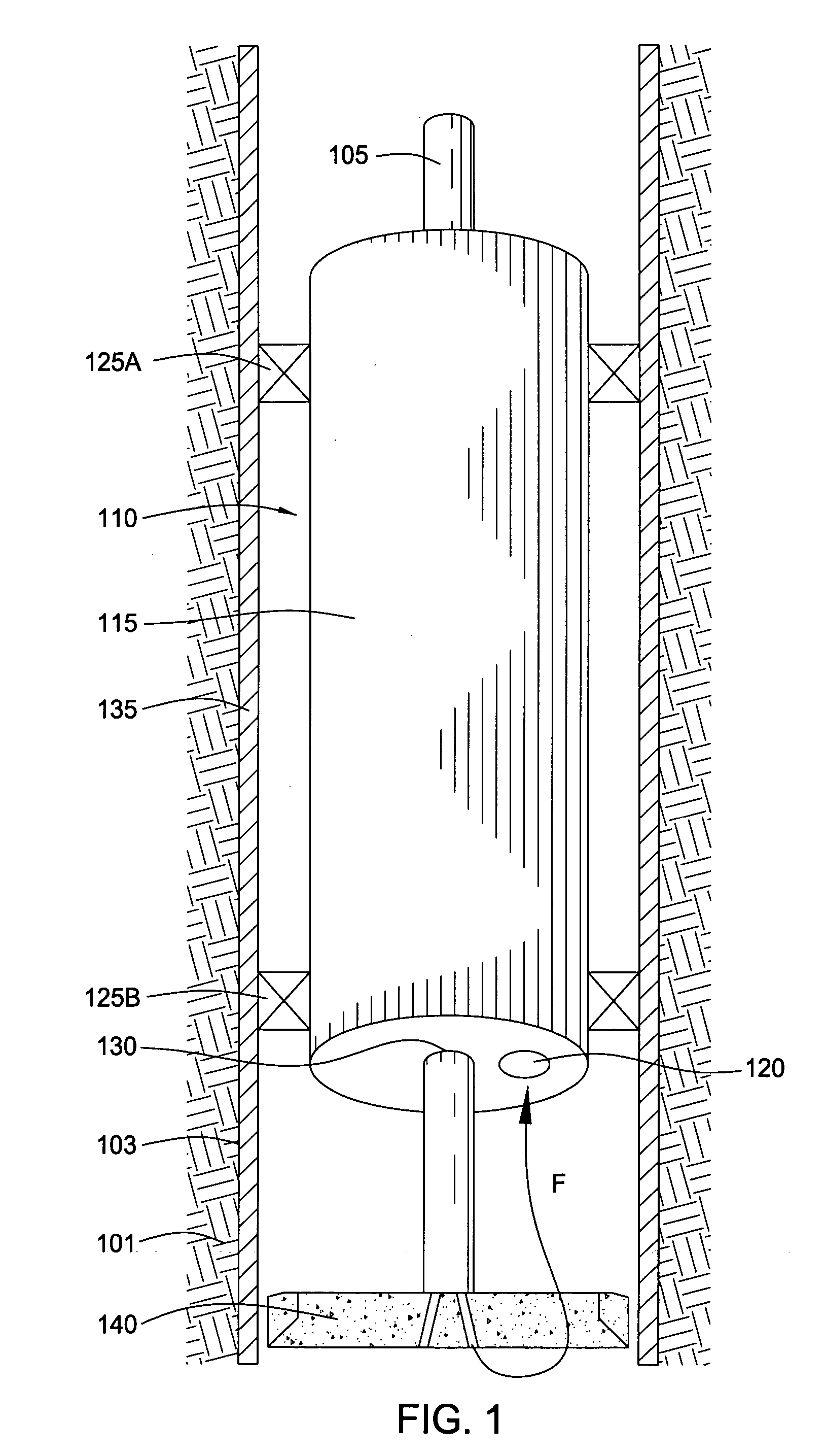
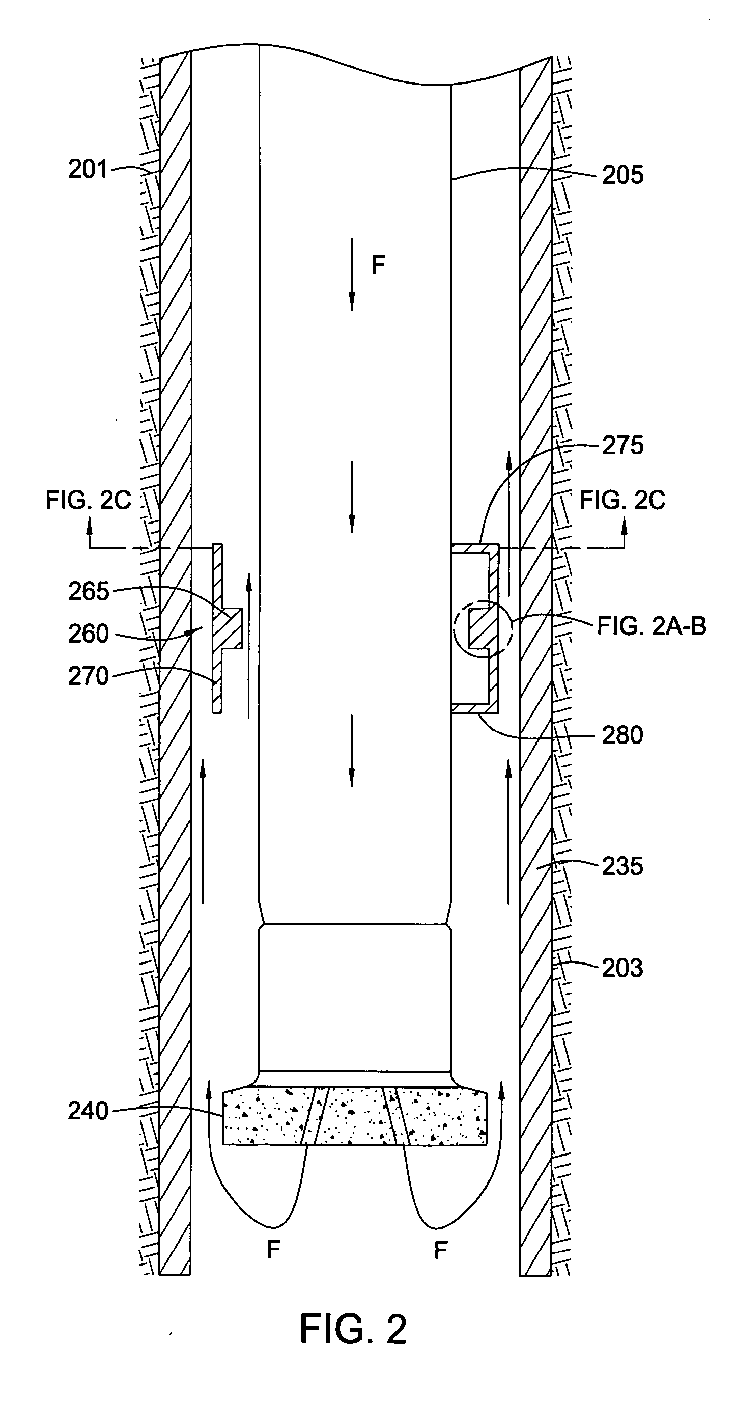
[0054] In embodiments of the present invention, a downhole choke is utilized to affect fluid pressure within the wellbore. FIGS. 1-3 show embodiments of downhole chokes which reduce the pressure of drilling fluid circulating up through the annulus between the drill string and the wellbore above the downhole chokes, while i...


PUM


Abstract

Embodiments of the present invention include methods and apparatus for dynamically controlling pressure within a wellbore while forming the wellbore. In one aspect, one or more pressure control apparatus are used to maintain desired pressure within the wellbore while drilling the wellbore. In another aspect, pressure is dynamically controlled while drilling using foam to maintain a substantially homogenous foam flow regime within the wellbore annulus for carrying cuttings from the wellbore.

Description

CROSS-REFERENCE TO RELATED APPLICATIONS [0001] This application is a continuation-in-part of co-pending U.S. patent application Ser. No. 10 / 958,734 filed on Oct. 5, 2004, which is herein incorporated by reference in its entirety. U.S. patent application Ser. No. 10 / 958,734 is a divisional of U.S. patent application Ser. No. 10 / 156,722 filed on May 28, 2002, now U.S. Pat. No. 6,837,313, which is incorporated by reference herein in its entirety.BACKGROUND OF THE INVENTION [0002] 1. Field of the Invention [0003] Embodiments of the present invention generally relate to managing pressure within a wellbore. More specifically, embodiments of the present invention relate to managing pressure within the wellbore relative to pressure within a surrounding earth formation. [0004] 2. Description of the Related Art [0005] To obtain hydrocarbon fluid production within an earth formation, a drill string is typically used to drill a wellbore of a first depth into the formation. The drill string incl...

Claims


Application Information

Patent Timeline
Patent Type & Authority Applications(United States)
IPC IPC(8): E21B21/00
CPCE21B4/02E21B21/00E21B2021/006E21B21/14E21B33/14E21B21/08E21B21/085E21B33/13
Inventor TILTON, FREDERICK T.HAUGEN, DAVID M.SMITH, KEVIN W.BRUNNERT, DAVID J.BAILEY, THOMAS F.FULLER, TOMROOYAKKERS, ROY W.BANSAL, RAM K.SKINNER, GRAHAM
Owner WEATHERFORD TECH HLDG LLC
Learn More