Dental hygiene pulsatory slit apparatus

a pulsatory slit and dental hygiene technology, applied in the field of dental hygiene pulsatory slit apparatuses, can solve the problems of cumbersome use of available devices, still significant problems, and encounter difficulties, and achieve the effect of no complicated mechanism and great use of oral or dental hygien

Inactive Publication Date: 2006-04-13
YANDE CHANDRAKANT R
View PDF6 Cites 122 Cited by
  • Summary
  • Abstract
  • Description
  • Claims
  • Application Information

AI Technical Summary

Benefits of technology

[0010] This revolutionary invention is simple, having no complic

Problems solved by technology

These are useful but they encounter some difficulties.
The use of electricity near by water means which last for a short time and replacing them are expensive and use of the

Method used


Image

  • Dental hygiene pulsatory slit apparatus
  • Dental hygiene pulsatory slit apparatus
  • Dental hygiene pulsatory slit apparatus

Examples


Embodiment Construction

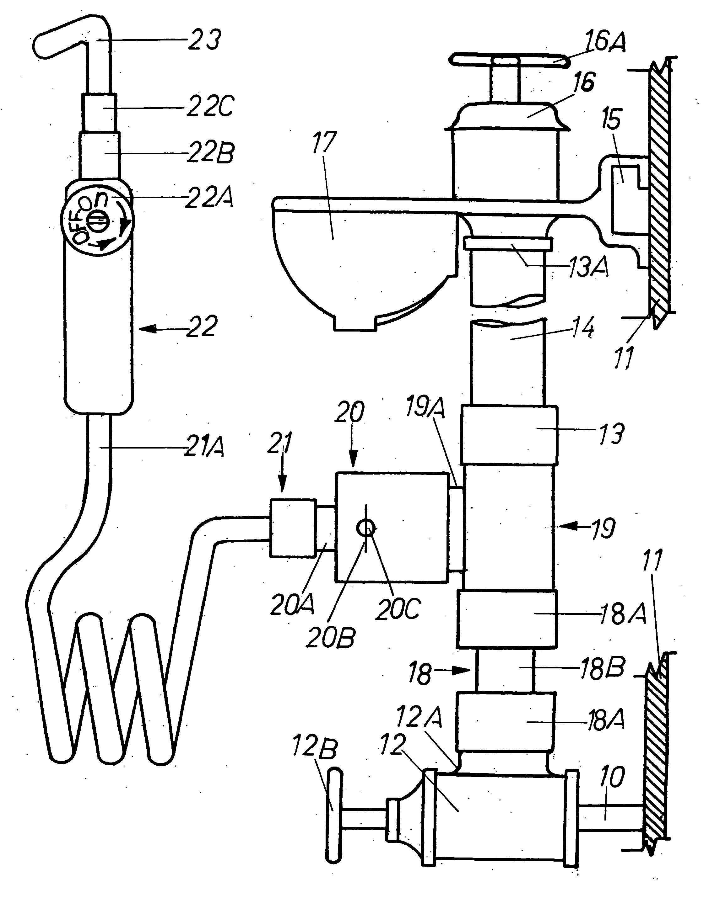
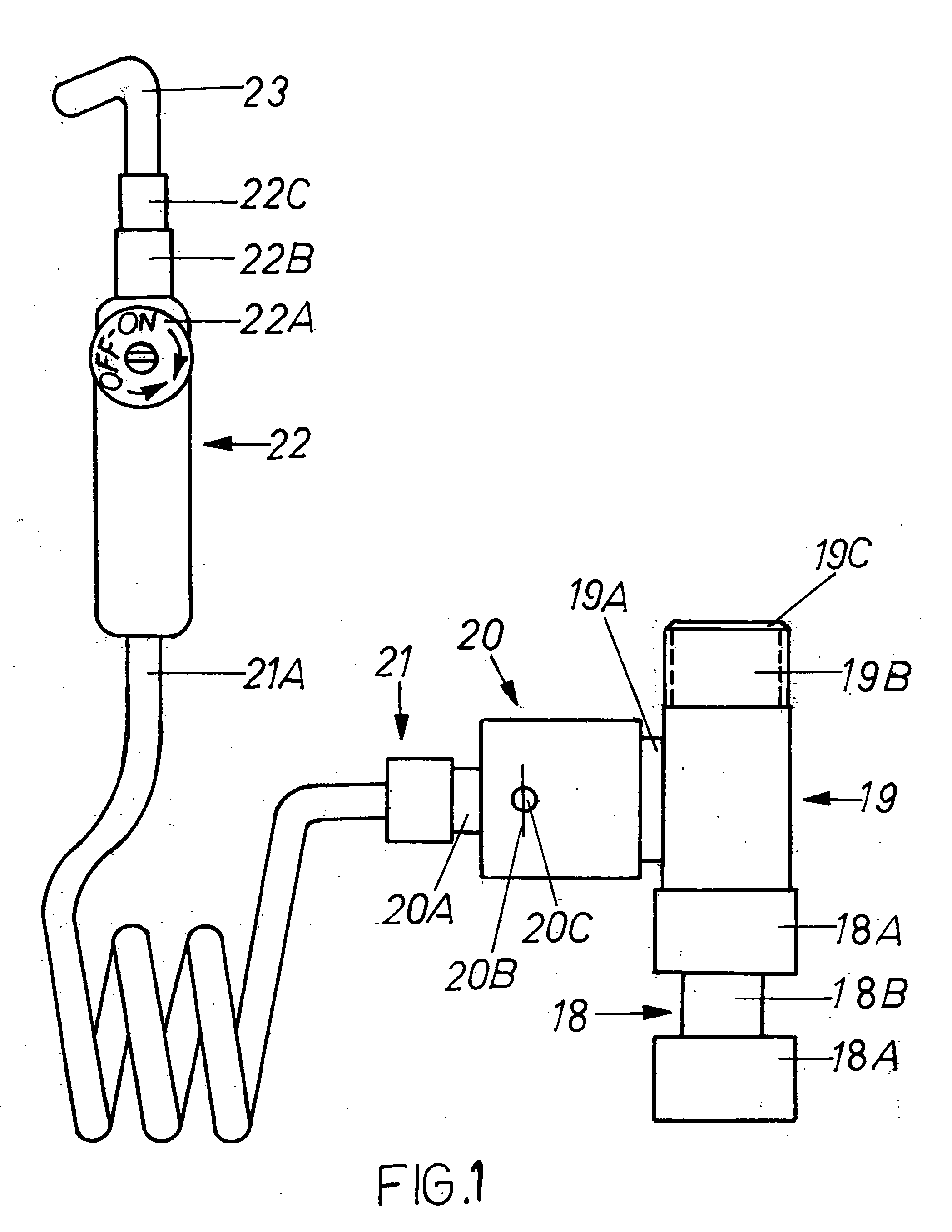
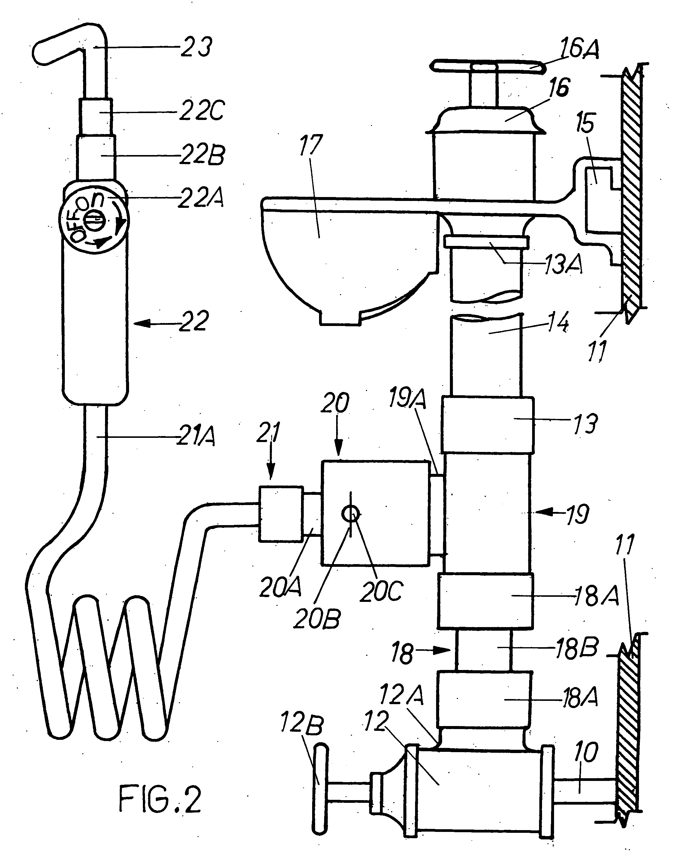
[0033] In accordance with the present invention, the novel dental hygiene pulsatory slit apparatuses or units are shown in FIG. 1 and FIG. 3 respectively. The specific wordings are used in these descriptions for fulfilling the requirements only and it is not to be assumed as a limitation on the present invention.

[0034] For designated numbers and letters refer to the checklist. Furthermore, refer to the flowchart of the connections of the apparatuses shown in FIGS. 1,2,3 and 4 respectively.

[0035]FIG. 1 and FIG. 3 show perspective views of a basic version of the invention.

[0036] Referring to FIG. 1, an arrow 18 is a body of a bi-functional coupling connected to a tri-functional connector body 19. The body 19 is connected to an open-shutoff orifice valve body 20. A flexible and inflexible conduit assembly body 21 is connected to the open-shutoff orifice valve body 20

[0037] A terminal 21A of the assembly 21 is connected to a hand held cylindrical device body 22.

[0038] A directional ...


PUM


Abstract

An improved pulsatory slit apparatus to be connected for a dental hygiene. Supply line valves to be shutoff before connecting the devices. By disconnecting cold water conduit of a faucet of a sink from a domestic cold water supply line valve in a bathroom and reconnecting it to 19B, and by connecting the valve to 18A as shown in FIG. 1, it becomes an operative device as shown in FIG. 2. For a combination of hot and cold water, by disconnecting the cold water supply line valve as previously stated and by disconnecting the hot water conduit of the faucet from the hot water supply line valve in a bathroom and reconnecting the cold water connector to a top right side straight end 19B of an apparatus and the hot water connector to a top left side straight end 19B of the apparatus as shown in FIG. 3, this process completes a connection of the faucet and the apparatus. To complete the connection of the apparatus and the supply lines it requires two conduits of the same size hexagonal or of similar configurational nuts at the four ends of the conduits. One conduit connects to the cold water supply line valve and the other end of the conduit connects to the bottom right side straight end 19B of the apparatus. The second conduit connects to the hot water supply line valve and the other end of the conduit connects to a bottom left side straight end 19B of the apparatus as shown in FIG. 3. This process completes the connections of the supply lines of the apparatus and it becomes an operative device as shown in FIG. 4. An open-shutoff orifice valve directs the water to a hand held cylindrical device. The hand held cylindrical device having a pressure control valve assembly and the assembly having an off-on pressure control dial. A nipple of a slit orientation is attachable to the hand held cylindrical device. The hand held cylindrical device with the pressure control dial at fingertip redirects the water under pressure to the nipple for users' teeth and gums. The nipple provides the users strong pulsatory slits of thousands of tiny pulses, not just droplets as described in the prior arts. The pressure control dial let the users control the desirable pressure for comfortable use of the dental hygiene pulsatory slit apparatus.

Description

FIELD OF THE INVENTION [0001] This invention relates to dental hygiene pulsatory slit apparatuses, and particularly relates to a controllable dial of a hand held cylindrical device. Still particularly relates to the slit of a nipple of thousands of pulsating surges to improve dental hygiene and to cleanse, to dislodge food particles from teeth and to massage the gums. Furthermore, it relates to improvements in oral hygiene device. More particualary it pertains to the dental hygiene pulsatory slit apparatus operated by the energy from the water pressure. BACKGROUND OF THE INVENTION [0002] In the prior arts of an oral irrigators and other related dental hygiene devices, no invention for use with a cold water shutoff valve of the domestic supply line and with cold and hot water shutoff valves, as a combination, of the supply lines under a sink in a bathroom have been invented for a dental hygiene. [0003] Originally many pateneted devices provide water pulsating jets or nozzles for dent...

Claims


Application Information

Patent Timeline
IPC IPC(8): A61H13/00
CPCA61C17/0214A61H13/005A61C17/032
Inventor YANDE, CHANDRAKANT R.
Owner YANDE CHANDRAKANT R
Why Eureka
Try Eureka