Inkjet recording apparatus

a recording apparatus and inkjet technology, applied in the field of inkjet recording apparatus, can solve the problems of inability to eject ink, inhibit the flow of ink, and produce failures of ejection in which no ink is ejected, and achieve the effects of reducing pressure variation, high pressure adjustment accuracy, and good print quality

Active Publication Date: 2010-04-08
FUJIFILM CORP
View PDF7 Cites 117 Cited by
  • Summary
  • Abstract
  • Description
  • Claims
  • Application Information

AI Technical Summary

Benefits of technology

[0026]According to this aspect of the present invention, it is possible to attenuate pressure variation caused by movement of the liquid by means of the flexible film and the gas chamber, and hence the pressure variation is not transmitted to the inkjet head and therefore good print quality can be ensured. Furthermore, highly accurate pressure adjustment can be achieved.
[0027]According to the present invention, by controlling the pressures in such a manner that a prescribed pressure differential is produced between the internal pressures of the first and second liquid chambers, it is possible to circulate the liquid from the first liquid chamber to the second liquid chamber though the inkjet head, while maint

Problems solved by technology

In particular, normally, a certain quantity of gas is dissolved into the ink (dissolved gas) and forms gas bubbles inside the ink flow channels and the recording head, which can give rise to negative effects such as inhibiting the flow of ink and producing ejection failures in which no ink is ejected.
However, in the composition described in Japanese Patent Application Publication No. 11-042795, since deaeration is performed after returning ink to a main tank in which ink is stored or to a sub tank in which ink is held temporarily, then consequently the circulated ink volume becomes large.
Therefore, it is necessary to provide a deaeration device having a large capacity and hence there is a drawback in that the apparatus costs become high.
Furthermore, there is a possibility that air will dissolve into the ink held in the main tank, and hence there is also a problem of decline in the deaeration efficiency.
Moreover, since the deaeration device is provided

Method used


Image

  • Inkjet recording apparatus
  • Inkjet recording apparatus
  • Inkjet recording apparatus

Examples


first embodiment

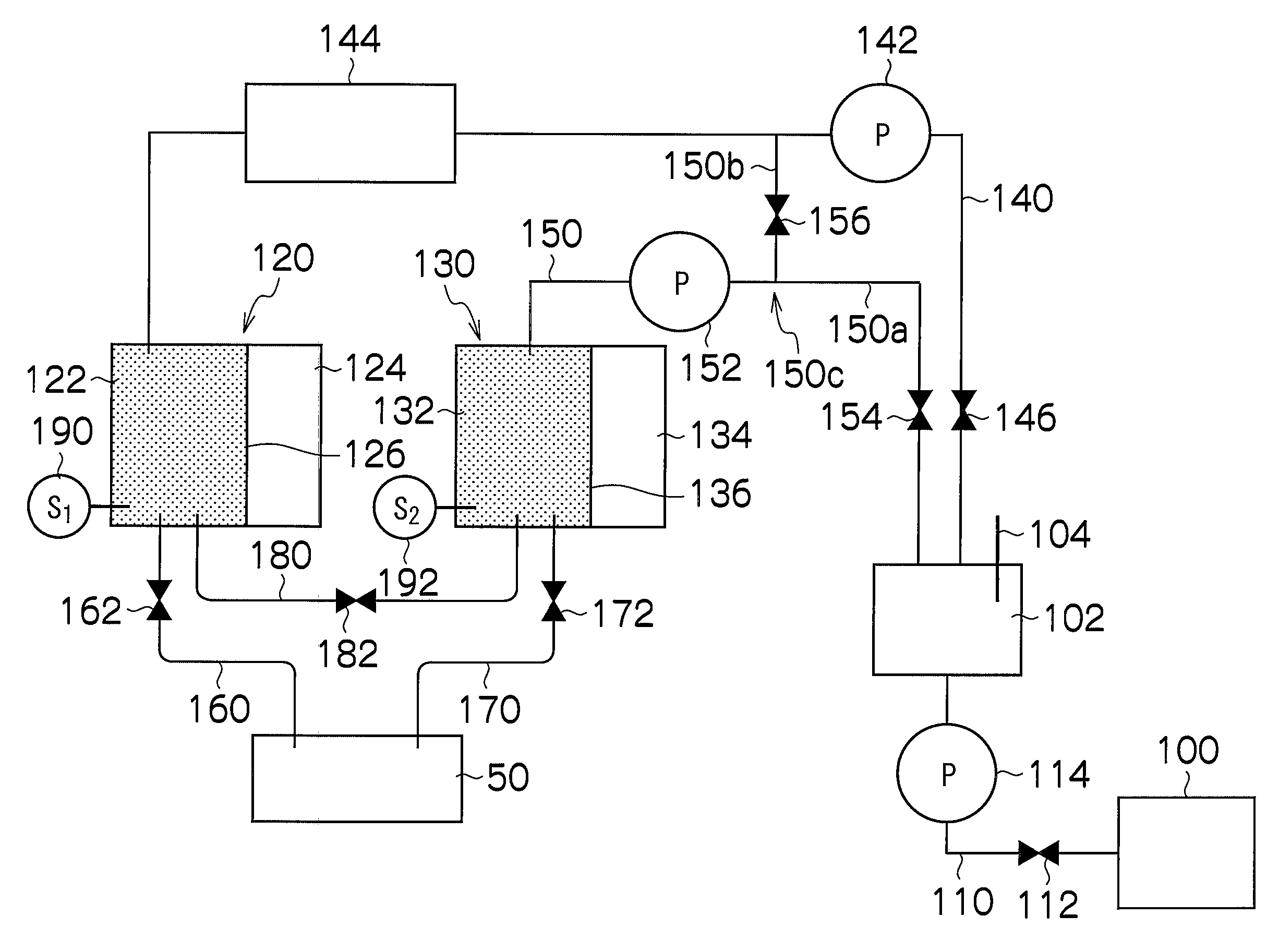
[0095]FIG. 7 is a schematic drawing showing the composition of an ink supply system according to a first embodiment of the present invention. In FIG. 7, in order to simplify the description, the ink supply system relating to only one color is depicted, but in the case of a plurality of colors, a plurality of similar compositions are provided.

[0096]As shown in FIG. 7, the ink supply system in the first embodiment principally includes: a main tank 100, a buffer tank 102, a supply sub tank 120 and a recovery sub tank 130.

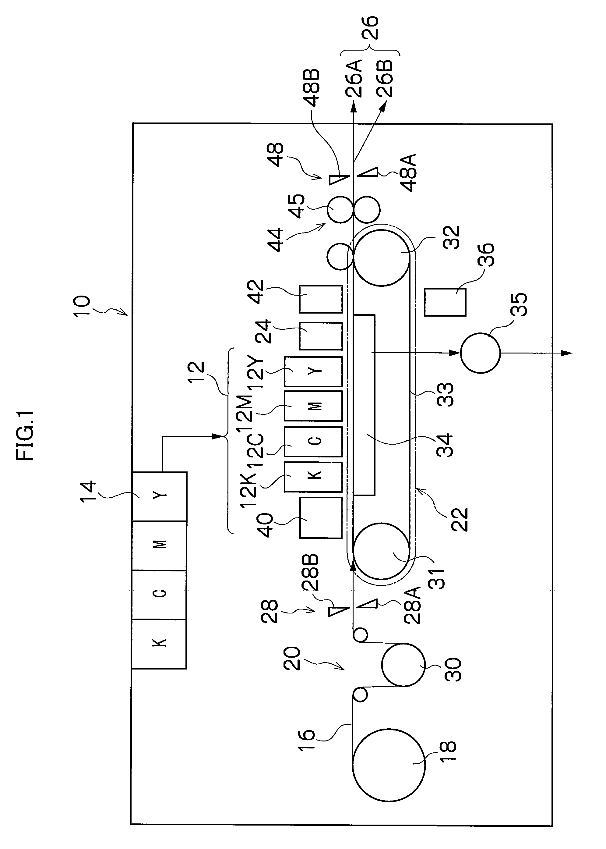
[0097]The main tank 100 is a base tank (ink supply source) which stores the ink for supplying to the head 50, and corresponds to the tank that is disposed in the ink storage and loading unit 14 shown in FIG. 1. One end of a flow channel 110 is connected to the main tank 100, and the other end of the flow channel 110 is connected to the buffer tank 102. In this flow channel 110, an opening and closing valve 112 and a pump 114 are provided in sequence from the upstream s...

second embodiment

[0137]Next, a second embodiment of the present invention will be described. Below, portions which are common with the first embodiment are not explained further, and the following description centers on the characteristic features of the present embodiment.

[0138]FIG. 8 is a schematic drawing showing the composition of an ink supply system according to the second embodiment of the present invention. In FIG. 8, parts which are common with FIG. 7 are denoted with the same reference numerals.

[0139]In the ink supply system according to the second embodiment, the other end of the flow channel 150 is connected to the buffer tank 102 without branching. In other words, in the second embodiment, a composition is adopted in which the first circulation path includes the buffer tank 102.

[0140]Furthermore, in the second embodiment, both ends of a circulation flow channel 200 are connected to the liquid chamber 122 of the supply sub tank 120 as shown in FIG. 8, instead of the bypass flow channel 1...

third embodiment

[0144]Next, a third embodiment of the present invention will be described. Below, portions which are common with the first and the second embodiments are not explained further, and the following description centers on the characteristic features of the present embodiment.

[0145]FIG. 9 is a schematic drawing showing the composition of an ink supply system according to the third embodiment of the present invention. In FIG. 9, parts which are common with FIG. 7 or FIG. 8 are denoted with the same reference numerals.

[0146]An ink consumption calculation unit 210 is provided in the ink supply system according to the third embodiment. The ink consumption calculation unit 210 calculates the volume of ink consumed by the head 50 (total ejection volume of the head) on the basis of the image data and the number of prints to be made (print number), and reports the result of this calculation to the pressure control unit 72a (see FIG. 6).

[0147]The pressure control unit 72a controls the driving of ...


PUM


Abstract

Inkjet apparatus includes: a tank; a first flow channel; a first liquid chamber; a second flow channel; a second liquid chamber; a first liquid movement; a second liquid movement device; a first pressure determination device; a second pressure determination device; a pressure control device which controls pressures in the first and second liquid chambers by respectively controlling the first and second liquid movement devices, in accordance with determination results of the first and second pressure determination devices, in such a manner that the internal pressures of the first and second liquid chambers respectively remain at the target pressures; a circulation path through which the liquid inside the first liquid chamber is circulated without passing through the inkjet head; and a deaeration device which is provided at an intermediate point of the circulation path and which removes dissolved gas.

Description

BACKGROUND OF THE INVENTION[0001]1. Field of the Invention[0002]The present invention relates to an inkjet recording apparatus, and more particularly, to technology for supplying satisfactory deaerated ink to an inkjet head.[0003]2. Description of the Related Art[0004]An inkjet recording apparatus that forms an image by ejecting ink from a recording head (an inkjet head) to a recording medium has many merits as follows. An image of high accuracy can be formed by a small recording head in which a plurality of nozzles are arranged at high density. Moreover, by aligning a plurality of recording heads and supplying different inks of a plurality of colors to the recording heads, a color image is obtained by means of a small and inexpensive composition. Furthermore, by aligning heads substantially in a line configuration, it is possible to record over large format recording medium having a broad width.[0005]In an inkjet recording apparatus of this kind, it is important that the ejection o...

Claims


Application Information

Patent Timeline
IPC IPC(8): B41J2/195B41J29/38
CPCB41J2/14233B41J2/175B41J2/18B41J29/38B41J2202/21B41J2002/14459B41J2202/12B41J2202/20B41J29/393
Inventor YOKOTA, YASUYOKATAKA, MASAHITOSHIBATA, HIROSHIKATADA, YUKO
Owner FUJIFILM CORP
Why Eureka
Try Eureka