
Blowing head, method for producing a blown film and blown film installation

A technology of blow molding die head and equipment, which is applied in blown film equipment and the field of making blown film

Inactive Publication Date: 2017-08-29
REIFENHAEUSER GMBH& CO KG MASCHFAB
View PDF4 Cites 0 Cited by
  • Summary
  • Abstract
  • Description
  • Claims
  • Application Information

AI Technical Summary

Problems solved by technology

[0007] EP 1 550 541 B1 in its figure 1 A plate-type screw distributor is also disclosed in ; however, the remainder of the invention relates to a different type of screw mandrel distributor, and in its Figure 4 it only discloses an axial screw distributor

Method used


Image

  • Blowing head, method for producing a blown film and blown film installation
  • Blowing head, method for producing a blown film and blown film installation

Examples


Embodiment Construction

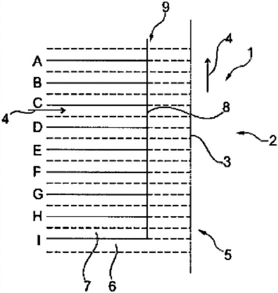
[0057] Compared to other types, figure 1 The blow molding die (1) in (only partly shown) comprises a plate-type screw distributor (2) with an extrusion axis (3). Nine helices (A, B, C, D, E, F, G, H, J) are sequentially arranged on mutually parallel layers along the extrusion direction (4), and each helix is ​​formed on two stacked plates (6 , 7) between plate packages (5) (exemplary numbers).

[0058] These spirals extend radially inward until the extrusion axis (3) enters the annular gap (8) leading to the pipe die (9).

[0059] During operation of the blow molding die (1), the melt stream produced by the extruder (not shown) is directed into nine spirals, where they are directed towards the annular gap ( 8) Flow. In this way, nine layers of membrane are produced in the annular gap (8). Starting from the input of the bottom screw (J) into the annular gap (8), a monolayer melt flow is generated that rises through the annular gap (8) in the extrusion direction (4). When rea...


PUM


Abstract

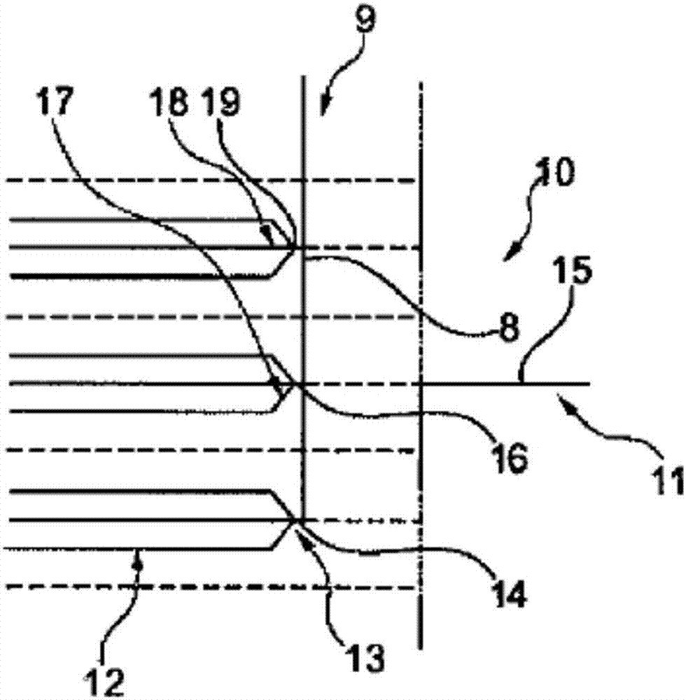
The invention relates to a blowing head, a method for producing a blown film and a blown film installation. Specifically, the invention relates to the use of plate spiral distributors (2) in blown film installations. It is proposed that the melt streams in a plate spiral distributor (2) are initially bundled (13, 17, 18) and then forwarded in a bundled manner to a common co-extrusion flow (8).

Description

technical field [0001] The invention relates to a blowing die head used for blown film equipment, a method for making blown film and a blown film equipment. Background technique [0002] Blown film equipment is well known and has proven its worth in the state of the art. [0003] In the extruder, the plastic pellets are liquefied and compressed (ie homogenized) by shearing. The plastic melt is fed to the blow mold through separate channels. In the blow molding head, the screw distributor distributes the plastic melt in layers into the annular gap leading to the annular gap nozzle. The multi-layer blown film tube emerges from the annular gap nozzle in the form of a melt, then solidifies at the freeze line, then lays flat, turns, partially reverses and finally rolls up. [0004] There are two common types of blow molding heads. The first is an axial spiral distributor, which is embodied as a conical spiral distributor or a cylindrical spiral distributor; the other is a pla...

Claims


Application Information

Patent Timeline
Patent Type & Authority Applications(China)
IPC IPC(8): B29C47/56B29C47/06B29C47/26B29C47/08B29C47/70B29C48/10B29C48/21B29C48/335B29C48/49B29C48/71
CPCB29C48/10B29C48/185B29C48/49B29C48/21B29C48/338B29C48/3363B29C48/2566B29C48/0018B29C48/71B29C48/30B29C48/3001B29C48/255B29L2023/001
Inventor 霍尔格·舒马赫贝恩德·施勒特
Owner REIFENHAEUSER GMBH& CO KG MASCHFAB
Learn More