Application of two-way adjustable fluid conveying device
A technology for fluid transportation and use, applied in the field of fluid transportation, can solve the problems of inability to change the direction of air in and out, single, only one-way exhaust to the outside of the shoe, and inability to exchange exhaust and air intake, etc., so as to achieve convenient use Effect
- Summary
- Abstract
- Description
- Claims
- Application Information
AI Technical Summary
Problems solved by technology
Method used
Image

Examples
Embodiment 1
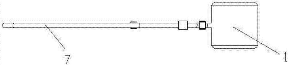
[0062] by figure 1 , figure 2 , image 3 It can be seen from the side view, top view, and overall effect diagram that the two-way adjustable fluid delivery device of the present invention first has a pressure airbag 1 (in practice, it is not limited to this pressure airbag 1, as long as it is elastic or retractable, and can be sucked in And all the airbags or containers that output fluid; and it can also be a water pump instead of its function), and the two main pipes 2 communicating with the pressure airbag 1. The pipes are elastic and apply External force can squeeze a flat hose, or other pipes that will merge and block after external force is applied. As shown in the figure, it includes a fluid switch A, figure 2 The middle fluid switch A is a key switch 10. The two main pipes 2 pass under the keys inside the key switch 10, and correspond to the two keys of the key switch 10 perpendicularly, so that the key of the key switch 10 is pressed down. It can just be pressed down ...
Embodiment 2
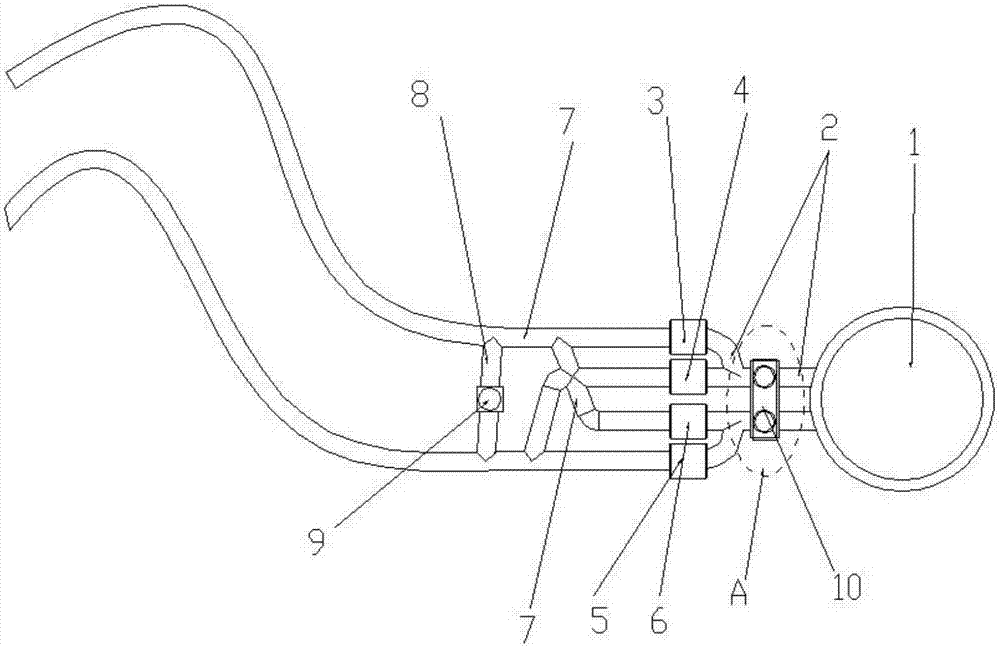
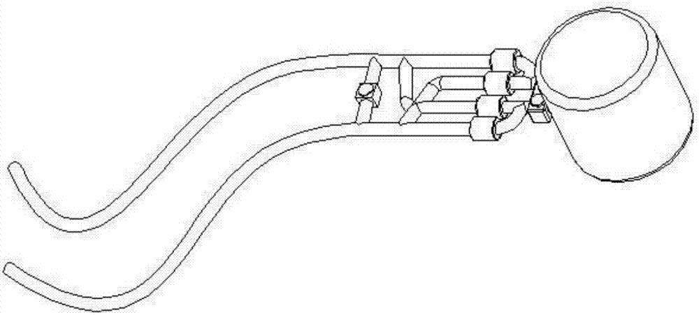
[0064] by Figure 4 to Figure 9 The side view, top view, partial enlarged view, and effect view point out another preferred embodiment of the present invention. Figure 4 , 5 , 6, 9 We can see that the two-way adjustable fluid delivery device of the present invention is composed of a pressure airbag 1, a main pipe 2, a one-way valve and a secondary pipe 7, and a fluid switch A. In addition to the connection and installation method and structure of the pressure airbag 1, the main pipeline 2, each one-way valve and the auxiliary pipeline 7; Image 6 Shown Figure 5 It can be seen from the enlarged perspective view of the part A in the middle that it includes a fluid switch A. Here, a fluid switch A is a wrench switch. As can be seen from the figure, a fixed housing 11 is installed on the two main pipes 2. Inside, there is a fixed seat 12 located in the middle of the two main pipes 2. Both the fixed seat 12 and the fixed housing 11 are fixed. The fixed housing 11 is adjacent to the ...
Embodiment 3
[0066] by Figure 10 to Figure 12 The above-mentioned plan view, partial enlarged view, and effect drawing point out another preferred embodiment of the present invention, except for the connection and installation method and structure of the pressure airbag 1, the main pipeline 2, each one-way valve, and the auxiliary pipeline 7; It can be seen from the figure that the difference from the previous two examples is that the fluid switch A set at the main pipe 2 of this embodiment is a lever switch. On the housing of the fixed housing 11, the middle positions on both sides of the vertical are respectively set There is a card position 19, which is horizontal to the center position of the two sides of the fixed housing 11 and perpendicular to the two main pipes 2. A fixed shaft 18 is provided. The central position of the fixed shaft 18 is movably connected with a pressure lever 17, Such as Picture 11 As shown, when in use, the pressure lever 17 is pressed down to both sides with th...
PUM
 Abstract
Description
Claims
Application Information
 - R&D
- Intellectual Property
- Life Sciences
- Materials
- Tech Scout
- Unparalleled Data Quality
- Higher Quality Content
- 60% Fewer Hallucinations
Browse by: Latest US Patents, China's latest patents, Technical Efficacy Thesaurus, Application Domain, Technology Topic, Popular Technical Reports.
© 2025 PatSnap. All rights reserved.Legal|Privacy policy|Modern Slavery Act Transparency Statement|Sitemap|About US| Contact US: help@patsnap.com