Purifier electric field structure and purifier
A purifier and electric field technology, applied in the field of purifiers, can solve the problems of poor plate-type electric field charging effect, inconvenient installation and maintenance, low effective pass rate, etc., to reduce cleaning frequency, simple production and increase charging time. Effect
- Summary
- Abstract
- Description
- Claims
- Application Information
AI Technical Summary
Problems solved by technology
Method used
Image

Examples
Embodiment 1
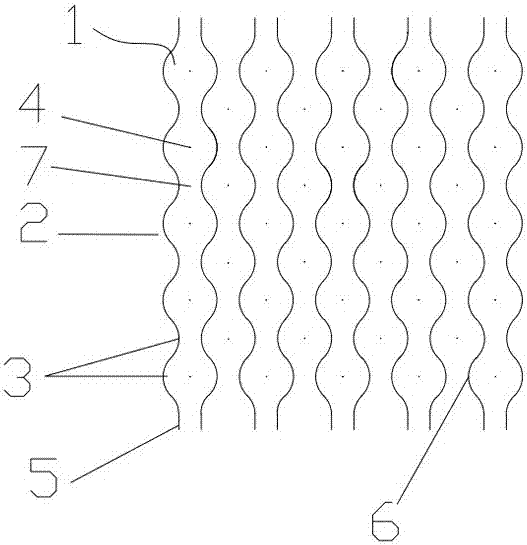
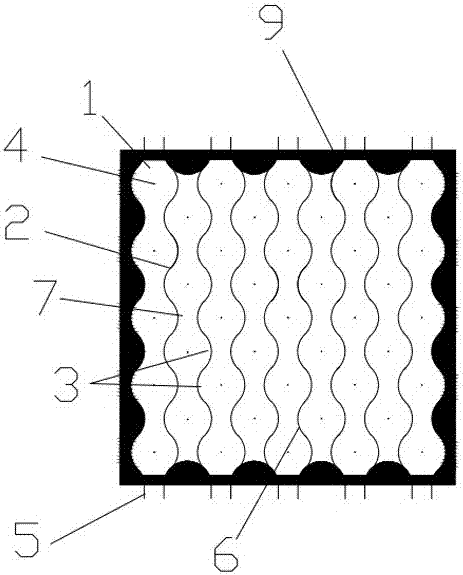
[0047] exist figure 1 , figure 2 In the described embodiment, a purifier electric field structure includes:
[0048] A number of evenly distributed dust-collecting pole units 1; the dust-collecting pole unit 1 is surrounded by a number of uniformly arranged dust-collecting plates 2; the dust-collecting plate 2 is a wave-shaped plate; the two board surfaces of the dust-collecting plate 2 are A number of dust-collecting pole enclosure grooves 3 are provided, and the dust-collection pole enclosure grooves 3 on the two board surfaces are alternately arranged; the dust-collection pole enclosure grooves 3 are arc-shaped grooves; The dust collecting pole enclosing groove 3 is respectively surrounded with the dust collecting pole enclosing groove 3 on the adjacent dust collecting plate 2 to form the dust collecting pole unit 1; the dust collecting pole enclosing groove 3 is on the other surface of the dust collecting plate 2 Wave bulges 6 are formed, and the wave bulges 6 on two ad...
Embodiment 2
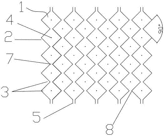
[0056] exist image 3 , Figure 4 In the described embodiment, a purifier electric field structure includes:
[0057] A number of evenly distributed dust-collecting pole units 1; the dust-collecting pole unit 1 is surrounded by a number of uniformly arranged dust-collecting plates 2; the two board surfaces of the dust-collecting plate 2 are respectively provided with a number of dust-collecting pole enclosing grooves 3 , and the dust-collecting pole enclosure grooves 3 on the two board surfaces are staggered; the dust-collecting plate 2 is a zigzag plate; the dust-collecting pole enclosure groove 3 is a triangular groove; The bending angle of the plate is 90 degrees, that is, the included angle of the 3 triangles surrounding the dust collecting pole is 90 degrees. The dust collecting pole enclosing grooves 3 on the two board surfaces of the dust collecting plate 2 are respectively enclosed with the dust collecting pole enclosing grooves 3 on the adjacent dust collecting plat...
Embodiment 3
[0065] exist Figure 5 , Image 6 In the described embodiment, in figure 1 , figure 2 In the described embodiment, a purifier electric field structure includes:
[0066] A number of evenly distributed dust-collecting pole units 1; the dust-collecting pole unit 1 is surrounded by a number of uniformly arranged dust-collecting plates 2; the two board surfaces of the dust-collecting plate 2 are respectively provided with a number of dust-collecting pole enclosing grooves 3 , and the dust-collecting pole enclosure grooves 3 on the two board surfaces are staggered; the dust-collecting plate 2 is a zigzag plate; the dust-collecting pole enclosure groove 3 is a triangular groove; The bending angle of the plate is 120 degrees, that is, the included angle of the 3 triangles surrounding the dust collecting pole is 120 degrees. The dust collecting pole enclosing grooves 3 on the two board surfaces of the dust collecting plate 2 are respectively enclosed with the dust collecting pole...
PUM
 Abstract
Description
Claims
Application Information
 - R&D Engineer
- R&D Manager
- IP Professional
- Industry Leading Data Capabilities
- Powerful AI technology
- Patent DNA Extraction
Browse by: Latest US Patents, China's latest patents, Technical Efficacy Thesaurus, Application Domain, Technology Topic.
© 2024 PatSnap. All rights reserved.Legal|Privacy policy|Modern Slavery Act Transparency Statement|Sitemap