Window hole combined mold for prefabricated components

A technology of combining molds and prefabricated components, applied in the directions of ceramic forming cores, ceramic forming mandrels, etc., can solve problems such as inability to realize structures

Active Publication Date: 2017-09-01
HEFEI ZHONGBAO MACHINERY MFG
View PDF5 Cites 4 Cited by
  • Summary
  • Abstract
  • Description
  • Claims
  • Application Information

AI Technical Summary

Problems solved by technology

The problem with the window mold with the above structure is that when the window mold is put into the mold cavity of the wall panel mold, the laying of the steel skeleton and the cement pouring are all carried out in the space between the window mold and the wall panel mold
Obviously, if the overall hoisting process is adopted, the vertical hoisting direction of the window hole mold just interferes with the arrangement of the return slope and the drip tank, which is the main reason why most prefabricated building components cannot realize the above structure

Method used


Image

  • Window hole combined mold for prefabricated components
  • Window hole combined mold for prefabricated components
  • Window hole combined mold for prefabricated components

Examples


Embodiment Construction

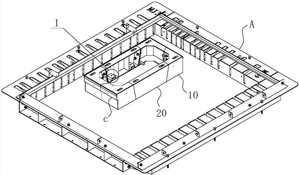
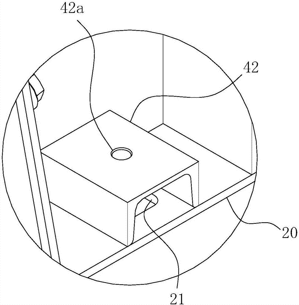
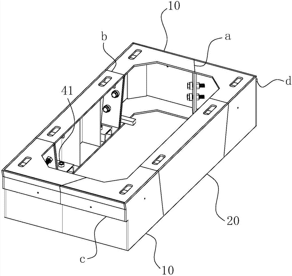
[0029] For ease of understanding, here in conjunction with accompanying drawing, the concrete structure of the present invention and working mode are further described as follows:

[0030] The specific structure of the present invention refers to Figure 1-6 As shown, it includes a mold body for placement in the mold cavity of wall panel mold A. When in use, the mold body is the same as the wallboard mold A, and is placed horizontally on a certain mold surface, which is referred to as "base surface" here. The aforementioned “vertical direction” corresponds to the direction perpendicular to the base plane. When the mold body and wallboard mold A are as a whole figure 1 When shown on the base surface, the space between the mold body and the wallboard mold A has just formed a "back"-shaped groove-like pouring area for cement pouring. After laying steel bars, pouring cement and even waiting for the cement to harden in the pouring area, remove the mold body and wallboard mold A ...


PUM


Abstract

The invention belongs to the technical field of building products, and in particular, relates to a window hole combined mold for prefabricated components. The mold comprises a mold body; the outer wall of the mold body forms a mold cavity surface; a vertical section is arranged on two parallel straight edges of the mold body, and two straight edge sections are arranged on the other two parallel straight edges in the vertical direction, so that the mold body is divided into four sets of angular end submolds and two sets of straight edge submolds; the angular end submolds are L-shaped to form four angular ends of the mold body; and on a projection in the vertical direction, a projection line formed by the vertical section is parallel to a direction pointed by the tip end of one cut angular end submold. The mold has the advantages of simple mold disassembly, convenient and fast operation and low manufacturing cost, can effectively prevent the concrete damage phenomenon at the inside corner parts of window holes to reduce or even eliminate later repair cost, and meanwhile, can realize once forming effect of water return slopes and water dripping grooves in the window holes.

Description

technical field [0001] The invention belongs to the technical field of building products, and in particular relates to a window hole combination mold for prefabricated components. Background technique [0002] In recent years, with the development of the economy, the construction industry has paid more and more attention to energy consumption and environmental pollution. The construction of traditional reinforced concrete structures in the field of construction often adopts on-site wet work. This construction method not only consumes a lot of wood as the bottom formwork and supporting materials, but also consumes a lot of energy, low construction efficiency, and long construction time. Noise and dust are produced, and at the same time, there is great pollution to the surrounding environment. Therefore, in recent years, the construction field has begun to introduce the concept of modular houses. Modular houses are different from traditional house construction. Usually, many...

Claims


Application Information

Patent Timeline
Patent Type & Authority Applications(China)
IPC IPC(8): B28B7/30B28B7/28
CPCB28B7/285B28B7/30
Inventor 邵徽斌高君谢其盛李建来孙效明高则炎
Owner HEFEI ZHONGBAO MACHINERY MFG
Why Eureka
Try Eureka