
Decorative plate

A technology for decorative panels and card slots, applied in floors, coverings/linings, buildings, etc., can solve the problems of obvious joints of decorative panels, large material loss ratio, cumbersome decoration, etc., achieve good support and reinforcement, and save energy Material, the effect of improving accuracy and firmness

Pending Publication Date: 2017-09-01
唐相平
View PDF14 Cites 4 Cited by
  • Summary
  • Abstract
  • Description
  • Claims
  • Application Information

AI Technical Summary

Problems solved by technology

Traditional building materials and traditional construction methods cannot avoid the cooperation of auxiliary materials such as base boards, wooden strips, keels, glue, paint, etc. for decoration. The decoration is cumbersome, time-consuming, and the cost is too high (materials and labor are the decoration costs), and The proportion of material loss is relatively large, the joints of decorative panels are obvious, and glue and paint will volatilize harmful gases that affect health. Therefore, it is urgent to develop a new type of decorative panel that is reliable in quality, easy to install, and does not require glue or paint.

Method used


Image

  • Decorative plate
  • Decorative plate
  • Decorative plate

Examples


Embodiment Construction

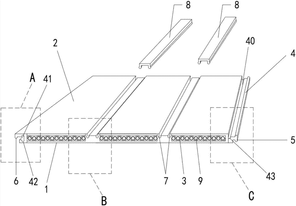
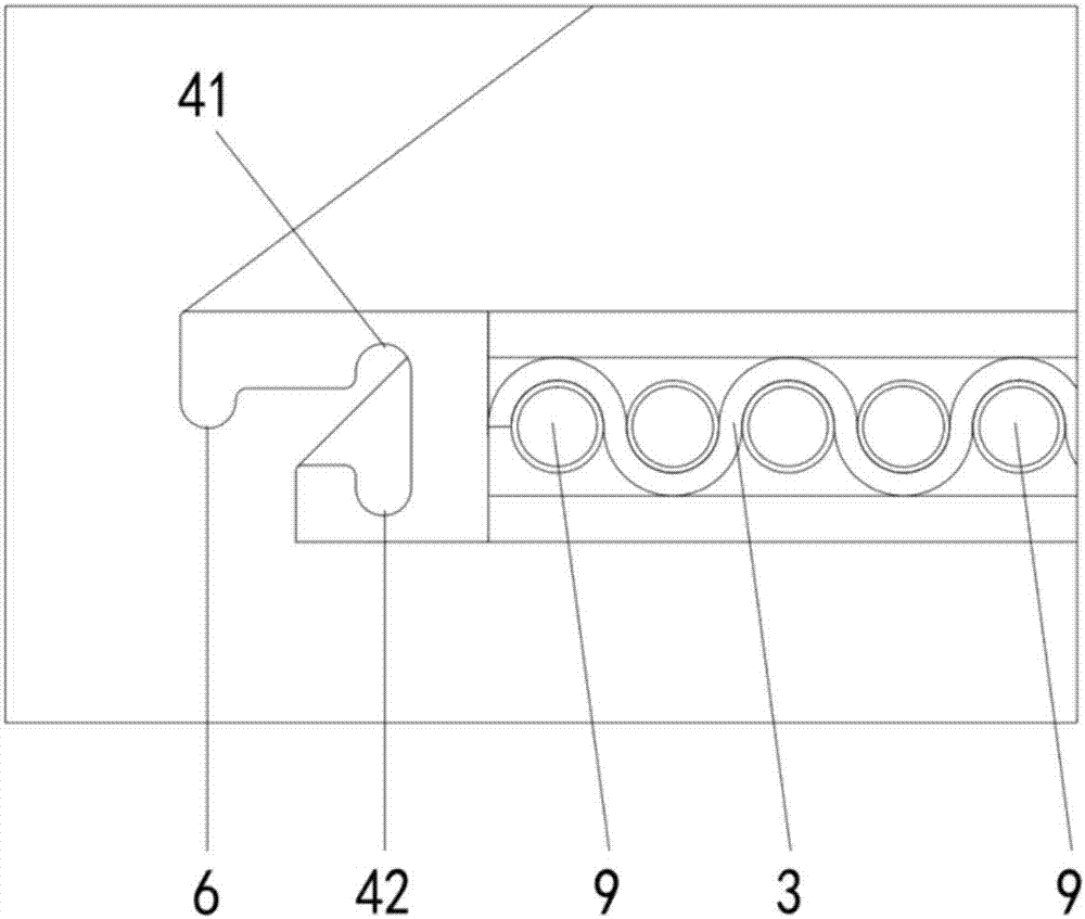
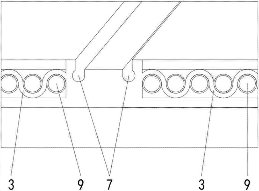
[0029] see Figure 1-6 , a decorative plate, which includes a surface layer 1 and a bottom surface 2, there is an interlayer 3 with a combination of waves and cylindrical holes in the cross section between the surface layer 1 and the bottom surface 2, which is formed by a high-temperature and high-pressure extrusion die of a screw, and then passed through It is formed by cooling and shaping. The left and right sides of the decorative plate are respectively provided with snap-in parts 4, 5, 6 and slots 41, 42, 43 that can be snap-connected to each other. The snap-in parts 4, 5, 6 and The card slots 41, 42, 43 are three-slot and three-buckle front and back buckle structures (see Figure 4 ), the clamping part 4 and the clamping part 5 are in a symmetrical shape, and a groove 40 and a clamping groove 43 are continuously provided on the clamping part 4 along the direction of the bottom surface 2; on the other side of the plate, a clamping part 6 is provided , and card slot 41 and...


PUM


Abstract

The invention discloses a decorative plate which comprises a surface layer, an interlayer and a bottom face. The interlayer with the cross section being formed by combining wavy holes and cylindrical holes exists between the surface layer and the bottom face. The decorative plate is formed in the mode that that microlite power and PE power are fixed according to a proportion, shaped through a screw high temperature and high pressure extrusion mold and subjected to cooling sizing. The left side and the right side of the decorative plate are separately provided with clamping parts and clamping grooves, wherein the clamping parts and the clamping grooves can be connected in a clamping fit mode. The clamping parts and the clamping grooves are provided with positive and negative inverse buckling structures. The extending direction of the clamping parts and the clamping grooves is consistent with the extending direction of crests or troughs of the interlayer. The surface of the bottom face is provided with a plurality of buckling part clamping grooves parallelly formed at intervals. The buckling part clamping grooves are internally matched with buckling parts clamped into the buckling part clamping grooves. The extending direction of the buckling part clamping grooves and the buckling parts is consistent with the extending direction of the crests and the troughs of the interlayer. The decorative plate can be conveniently spliced and fixed in a seamless mode, is green and environmentally friendly, saves energy and can remarkably improve decorative efficiency and quality.

Description

technical field [0001] The invention relates to the field of decoration and building materials, in particular to a decorative plate. Background technique [0002] In construction projects and furniture decoration, it is often necessary to assemble ceilings, wall panels, and floors. Under the premise of ensuring the installation quality, energy saving and fast installation must be fully realized to improve decoration efficiency and save decoration costs. Traditional building materials and traditional construction methods cannot avoid the cooperation of auxiliary materials such as base boards, wooden strips, keels, glue, paint, etc. for decoration. The decoration is cumbersome, time-consuming, and the cost is too high (materials and labor are the decoration costs), and The proportion of material loss is relatively large, the joints of decorative panels are obvious, and glue and paint will volatilize harmful gases that affect health. Therefore, it is urgent to develop a new t...

Claims


Application Information

Patent Timeline
IPC IPC(8): E04F13/074E04F13/076E04F13/077E04F13/24
CPCE04F13/0835E04F13/0866E04F13/0869E04F13/0894E04F13/18E04F2201/03E04F2201/04E04F2290/023
Inventor 唐相平
Owner 唐相平
Learn More