Template docking fixture

A clamp and formwork technology, which is applied to the connection parts of formwork/formwork/work frame, the preparation of building components on site, and construction, etc., can solve problems such as formwork displacement, and achieve accurate docking position, flexible rotation, and convenience. The effect of installing the fixed seat plate

Inactive Publication Date: 2019-07-26
徐州致诚会计服务有限公司
View PDF5 Cites 0 Cited by
  • Summary
  • Abstract
  • Description
  • Claims
  • Application Information

AI Technical Summary

Problems solved by technology

[0003] The problem to be solved by the present invention is to provide a formwork docking jig, which can solve the problem that the formwork is directly connected and fastened by bolts, which easily causes the formwork to shift

Method used


Image

  • Template docking fixture
  • Template docking fixture
  • Template docking fixture

Examples


Embodiment Construction

[0017] The present invention will be described in further detail below in conjunction with accompanying drawing embodiment:

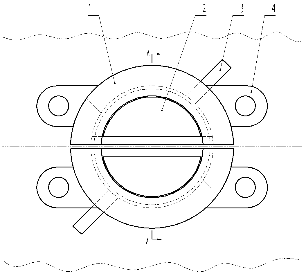
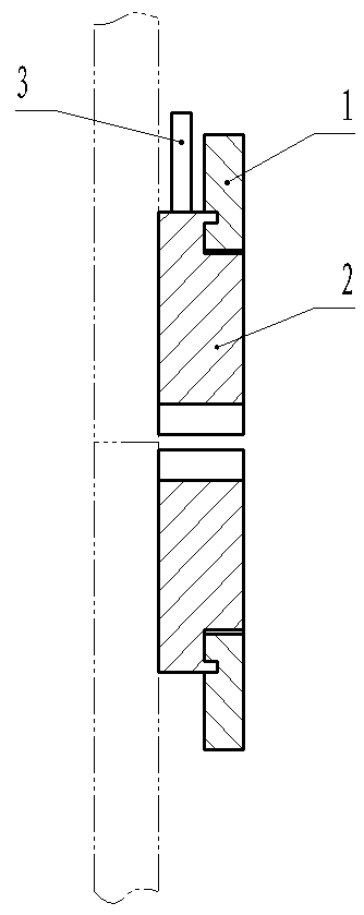
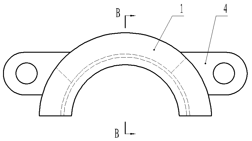
[0018] Such as figure 1 , figure 2 The template docking jig shown includes two symmetrically arranged fixed seat plates 1 and two movable blocks 2, the fixed seat plate 1 is connected with two installation ear plates 4, and the installation ear plates 4 are provided with installation holes The opposite sides of the two fixed seat plates 1 have arc-shaped grooves, and the movable block 2 has an arc-shaped surface that matches the arc-shaped grooves. The guide rail of the slot, the movable block 2 has a convex line that matches the guide rail, the outer side of the convex line of the movable block 2 is connected with a handle 3, and the handle 3 protrudes from the outside of the fixed seat plate 1, and the fixed seat plate 1 is provided with a limit handle. Put 3 swing limit slots, such as image 3 , Figure 4 , Figure 5 , Figure 6 As shown; the ...


PUM


Abstract

The invention discloses a formwork butting fixture and relates to the technical field of building mounting members. The formwork butting fixture comprises two symmetrically-arranged fixed seat plates and two symmetrically-arranged movable clamping blocks. Arc-shaped grooves are formed in the opposite sides of the two fixed seat plates. The movable clamping blocks are provided with arc-shaped faces matched with the arc-shaped grooves. Guide rails surrounding the arc-shaped grooves are formed in the end faces of the fixed seat plates. The movable clamping blocks are provided with protruding strips matched with the guide rails. Handles are connected with the outer sides of the protruding strips of the movable clamping blocks and stretch out of the outer sides of the fixed seat plates. The fixed seat plates are provided with limiting grooves limiting swinging of the handles. Compared with the prior art, the handles are pulled to drive the movable clamping blocks to rotate by 90 degrees, thus the arc-shaped faces of the movable clamping blocks are matched with the arc-shaped grooves of the two fixed seat plates, the displacement phenomenon of formwork butting does not occur, and the butting positions of two formworks are accurate.

Description

technical field [0001] The invention relates to the technical field of building installation components, in particular to a formwork docking jig. Background technique [0002] Building formwork is a temporary support structure that enables concrete structures and components to be formed according to specified positions and geometric dimensions, maintains their correct positions, and bears external loads acting on them. The butt joint between the formwork and the formwork is usually directly fastened by bolts. Since there is a certain connection gap between the bolts and the formwork, it is easy to cause the formwork to shift during the butt joint. Contents of the invention [0003] The problem to be solved by the present invention is to provide a template docking jig, which can solve the problem that the templates are easily displaced by directly using bolts to fasten the docking between the templates. [0004] In order to solve the above-mentioned problems, the technical...

Claims


Application Information

Patent Timeline
Patent Type & Authority Patents(China)
IPC IPC(8): E04G17/00
CPCE04G17/00
Inventor 谢绪金
Owner 徐州致诚会计服务有限公司
Why Eureka
Try Eureka