Self-aligning torsion hinge

A self-aligning and torsion technology, which is applied to door/window accessories, wing leaf parts, wing leaf openers, etc., can solve the problems of inconsistent automatic centering, increased door opening resistance, and uneven shaft force. Achieve the effect of saving effort in the process of opening and closing the door body, reducing the resistance of opening the door, and uniform force on the shaft

Active Publication Date: 2017-09-01
XUCHANG ZHENGTE GATING TECH
View PDF7 Cites 1 Cited by
  • Summary
  • Abstract
  • Description
  • Claims
  • Application Information

AI Technical Summary

Problems solved by technology

[0003] The purpose of the present invention is to overcome the fact that it is difficult to ensure that the door body is consistent with the gap between the upper and lower door frames during the installation process of the current hinge, and that automatic centering cannot be realized, and installation misalignment occurs or the shaft is stressed under the action of the weight of the door. Uneven, the resistance to opening the door increases, causing severe wear on the shaft and may cause the problem of a larger door gap, and a self-aligning torsion hinge is provided, which is convenient for adjusting the gap between the upper and lower door gaps during installation , in the process of opening and closing the door body, the self-aligning of the shaft can be realized through the self-aligning ball, which can avoid the wear between the shaft and the hinge caused by the misalignment of the shaft due to the gravity of the door body, so that the door body can be opened and closed More labor-saving, prolonging the service life of the hinge

Method used


Image

  • Self-aligning torsion hinge

Examples


Embodiment 1

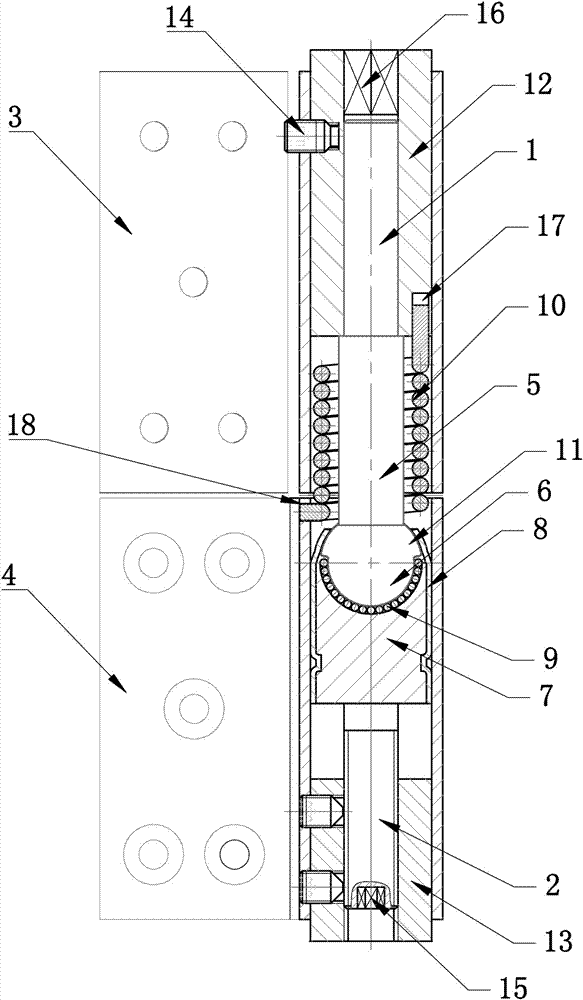
[0017] Embodiment 1: A kind of self-aligning torsion hinge, such as figure 1 As shown, it includes the mandrel and the upper leaf 3 and the lower leaf 4 that are set on the mandrel. The lower leaf is installed on the door frame, and the door body is installed on the upper leaf. The rotation of the door body can drive the upper leaf relative to the lower leaf. The leaf rotates to realize the opening and closing of the door body; the mandrel includes a first mandrel 1 and a second mandrel 2, the first mandrel 1 is covered with a first sleeve 12, and the second mandrel 2 The outer cover is equipped with a second shaft sleeve 13, and the mandrel and the shaft sleeve are fixedly connected by threads; the upper sheet 3 is installed outside the first mandrel through the first shaft sleeve, and the lower sheet 4 is installed on the outside of the first mandrel through the second shaft sleeve. Installed outside the second mandrel, the side walls of the upper leaf and the lower leaf are...


PUM


Abstract

The invention relates to a door installation connecting piece, in particular to a self-aligning torsion hinge. The self-aligning torsion hinge comprises a mandrel, an upper hinge leaf and a lower hinge leaf, wherein the mandrel is sleeved with the upper hinge leaf and the lower hinge leaf. The mandrel comprises a first mandrel body and a second mandrel body. The upper hinge leaf is installed on the first mandrel body, and the lower hinge leaf is installed on the second mandrel body. An aligning device is arranged between the first mandrel body and the second mandrel body. The aligning device comprises a ball rod arranged at the lower end of the first mandrel body, an aligning ball installed at the lower end of the ball rod, and a ball seat which is arranged at the upper end of the second mandrel body and used for installing the aligning ball. A wrapping pipe used for fixing the aligning ball is arranged outside the ball seat. A ball groove is formed in the upper end of the ball seat. A layer of roll balls are laid along the inner wall of the ball groove. The aligning ball can rotate in the ball groove through the roll balls. A torsional spring capable of making the upper hinge leaf generate rebound elastic force is arranged outside the ball rod in a sleeving mode. According to the self-aligning torsion hinge, a gap between an upper door slot and a lower door slot can be adjusted conveniently, self-alignment of the mandrel is achieved through the aligning ball, and the situation that abrasion is caused between the mandrel and the hinge due to dislocation of the mandrel can be avoided.

Description

technical field [0001] The invention relates to a door body installation connector, in particular to a self-aligning torsion hinge. Background technique [0002] The existing traditional door frame and door body are connected by hinges or hinges. Although this connection method is simple in structure, it is difficult to achieve the same gap between the door body and the upper and lower door frames during the installation process, and multiple adjustments are required. The door body causes troublesome installation and is more complicated; if there is an installation misalignment or error, the shaft of the hinge and the sleeve are not coaxial, and the shaft will experience uneven force, resulting in a certain degree of shaft wear; and in the door During the opening and closing process of the door body, the hinge is greatly affected by the weight of the door body, which causes serious wear between the shaft and the hinge, resulting in more and more force required to open and cl...

Claims


Application Information

Patent Timeline
IPC IPC(8): E05D7/04E05D11/04E05F1/00
CPCE05D7/0407E05D11/04E05F1/00
Inventor 赵泳淇李永建薛玉霞
Owner XUCHANG ZHENGTE GATING TECH
Why Eureka
Try Eureka