A calibrating device used for optical imaging equipment

A calibration device and optical imaging technology, applied in the field of optical instruments, can solve problems such as inconvenience to maintain parallelism, and achieve the effect of saving time, improving efficiency and maintaining stability

Active Publication Date: 2017-09-01
陈超
View PDF9 Cites 1 Cited by
  • Summary
  • Abstract
  • Description
  • Claims
  • Application Information

AI Technical Summary

Problems solved by technology

[0003] The purpose of the present invention is to provide a calibration device for optical imaging equipment, which has the advantage of being able to calibrate between structures, and solves the problem of inconvenient parallelism in the prior art

Method used


Image

  • A calibrating device used for optical imaging equipment
  • A calibrating device used for optical imaging equipment
  • A calibrating device used for optical imaging equipment

Examples


Embodiment Construction

[0019] The following will clearly and completely describe the technical solutions in the embodiments of the present invention with reference to the accompanying drawings in the embodiments of the present invention. Obviously, the described embodiments are only some, not all, embodiments of the present invention. Based on the embodiments of the present invention, all other embodiments obtained by persons of ordinary skill in the art without making creative efforts belong to the protection scope of the present invention.

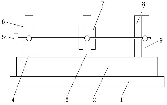
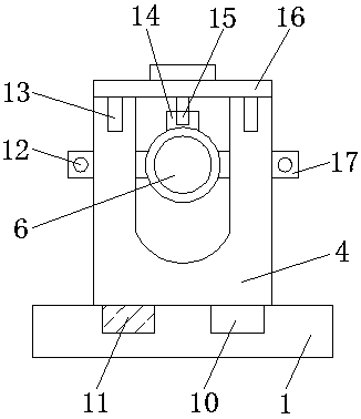
[0020] see Figure 1-4 , a calibration device for optical imaging equipment, including a base 1, the upper surface of the base 1 is sequentially provided with a first fixing frame 4, a second fixing frame 3 and a third fixing frame 9 from left to right, and the upper surface of the base 1 The two sides of both sides are all provided with chute 10, and base 1 is respectively first fixed frame 4, the second fixed frame 3 and the 3rd fixed frame 9 slidably connec...


PUM


Abstract

The invention discloses a calibrating device used for optical imaging equipment. The device comprises a pedestal. A first fixing frame, a second fixing frame and a third fixing frame are arranged in order from the left to the right on the pedestal; a first light transmission mirror is arranged on the inner side of the first fixing frame, and the inner side of the second fixing frame is provided with a second light transmission mirror; the third fixing frame is provided with an imaging device; the first light transmitting mirror is hinged with the first fixing frame through rotating shafts arranged on both sides thereof, and the two rotating shafts respectively penetrate through the both sides of the first fixing frame and are fixedly connected with a regulating plate; and the outer surface of the regulating plate is provided with regulating holes; and a horizontal adjusting device is arranged on the left side of the first fixing frame. According to the invention, the horizontal adjusting device and a vertical adjusting device can be respectively fixed in the horizontal direction and vertical direction of the equipment after equipment adjustment. Through cooperative usage between the devices, a mutually parallel relation of the equipment can be kept, and influences to experiment effects are avoided.

Description

technical field [0001] The invention relates to the technical field of optical instruments, in particular to a calibration device for optical imaging equipment. Background technique [0002] Optical instruments are a very important component category in the instrumentation industry, and are indispensable tools for observation, testing, analysis, control, recording and transmission in various fields of industrial and agricultural production, resource exploration, space exploration, scientific experiments, national defense construction and social life , especially the functions of modern optical instruments have become the extension and expansion of the functions of human brain nerves. The use of optical imaging devices has become very common, but the small imaging devices used by people in experiments are not easy to keep parallel to each other after adjustment. relationship, which affects the effect of the experiment. Contents of the invention [0003] The object of the p...

Claims


Application Information

Patent Timeline
Patent Type & Authority Applications(China)
IPC IPC(8): G02B7/00G02B7/02
CPCG02B7/00G02B7/02G02B7/023
Inventor 张素平
Owner 陈超
Why Eureka
Try Eureka