
Novel energy automobile battery protection damping mechanism

A technology of new energy vehicles and shock absorbing mechanisms, which is applied in the direction of battery pack parts, circuits, electrical components, etc., can solve problems such as the loss of function of the fixing mechanism, the impact of battery life, and the impact on the battery, so as to enhance the shock absorption effect and ensure shock absorption. Shock effect, the effect of reducing front and rear shaking

Active Publication Date: 2017-09-01
东莞市泓澈电子科技有限公司
View PDF5 Cites 32 Cited by
  • Summary
  • Abstract
  • Description
  • Claims
  • Application Information

AI Technical Summary

Problems solved by technology

[0002] The battery is the main energy storage device of the new energy vehicle and the key component of the electric vehicle, which directly affects the performance of the electric vehicle. The battery is located in the new energy vehicle, and a special fixing mechanism is often required to fix the battery. The battery will be subjected to different conditions in the vehicle The impact of road conditions, bumpy roads, sudden braking, etc., will cause the battery to collide with its fixing device, causing the inside of the battery to shake, and the life of the battery is likely to be affected by the vibration of the car. Affect the safety of the battery, therefore, it is necessary to design a battery protection device to reduce impact and prolong the service life

Method used


Image

  • Novel energy automobile battery protection damping mechanism
  • Novel energy automobile battery protection damping mechanism
  • Novel energy automobile battery protection damping mechanism

Examples


Embodiment Construction

[0016] The following will clearly and completely describe the technical solutions in the embodiments of the present invention with reference to the accompanying drawings in the embodiments of the present invention. Obviously, the described embodiments are only some, not all, embodiments of the present invention. Based on the embodiments of the present invention, all other embodiments obtained by persons of ordinary skill in the art without making creative efforts belong to the protection scope of the present invention.

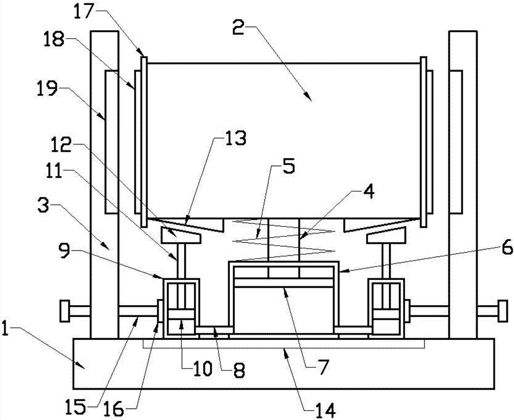
[0017] Please refer to the figure, in the embodiment of the present invention, a new energy vehicle battery protection and shock absorbing mechanism includes a fixed seat 1, a battery box 2 and a baffle 3; the battery box 2 is arranged above the fixed seat 1, and 1 and the battery box 2 are provided with a sealing box 6 and a piston cylinder 9; the sealing box 6 is fixed on the fixed seat 1, and a horizontal main piston 7 is arranged in the sealing box 6, and t...


PUM


Abstract

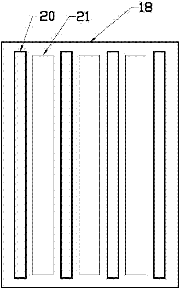
The invention discloses a novel energy automobile battery protection damping mechanism which comprises a fixed base, a battery tank and a baffle plate, wherein a sealing tank and a piston cylinder are arranged between the fixed base and the battery tank; a horizontal main piston is arranged inside the sealing tank; a vertical main piston rod is fixedly connected with the upper end of the main piston; a rubber tube is communicated with the bottom inside the sealing tank; the rubber tube extends into the piston cylinder; the piston cylinder is connected inside a chute in a sliding manner; a support block is fixed at the upper end of a secondary piston rod; a protection plate is fixed on a side wall of the battery tank; and a vertical inner plate body is fixed on the protection plate. As the main piston rod is pushed downwards through the battery tank, the main piston is moved downwards, the air inside the sealing tank is compressed, downward movement of the battery tank is retarded, then collision is avoided, and a damping function is achieved; and moreover, the air is compressed inside the sealing tank, the secondary piston inside the piston cylinder is moved upwards, then the support blocks contacts a pressing block, the battery tank is supported, the battery tank can be conveniently recovered, and the damping effect is enhanced.

Description

technical field [0001] The invention relates to the field of new energy vehicles, in particular to a new energy vehicle battery protection and damping mechanism. Background technique [0002] The battery is the main energy storage device of the new energy vehicle and the key component of the electric vehicle, which directly affects the performance of the electric vehicle. The battery is located in the new energy vehicle, and a special fixing mechanism is often required to fix the battery. The battery will be subjected to different conditions in the vehicle The impact of road conditions, bumpy roads, sudden braking, etc., will cause the battery to collide with its fixing device, causing the inside of the battery to shake, and the life of the battery is likely to be affected by the vibration of the car. It affects the safety of the battery. Therefore, it is necessary to design a battery protection device to reduce the impact and prolong the service life. Contents of the inve...

Claims


Application Information

Patent Timeline
IPC IPC(8): H01M2/10B60K1/04
CPCB60K1/04H01M50/20H01M50/256Y02E60/10
Inventor 谢灶福
Owner 东莞市泓澈电子科技有限公司
Learn More