
A self-controlled temperature type power transformation cabinet

A technology of substation cabinet and temperature type, which is applied in substation/power distribution device casing, substation/switch layout details, substation/switchgear cooling/ventilation, etc., which can solve fire, affect the reliability of internal equipment, and endanger operation personal safety issues

Active Publication Date: 2017-09-01
安徽伟合电子科技有限公司
View PDF7 Cites 5 Cited by
  • Summary
  • Abstract
  • Description
  • Claims
  • Application Information

AI Technical Summary

Problems solved by technology

The substation will release a large amount of heat during the working process, which will cause the temperature to rise and affect the reliability of the internal equipment. When the substation works at high temperature for a long time, it may even cause a fire hazard.
In addition, when the temperature difference between the inside and outside of the cabinet-type substation is too large, it is easy to accumulate moisture, which increases the humidity inside the substation, and the equipment in the cabinet-type substation is eroded by moisture, which affects the working stability and service life, and may even cause hazardous operations such as short circuits. hidden danger to personal safety

Method used


Image

  • A self-controlled temperature type power transformation cabinet

Examples


Embodiment Construction

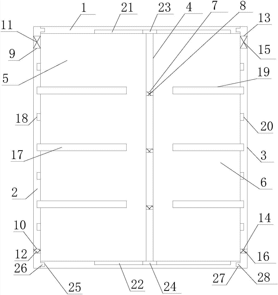
[0015] refer to figure 1 , the present invention proposes a self-temperature control type transformer cabinet, including a cabinet body and a controller, and the cabinet body includes a main body 1, a first cover plate 2 and a second cover plate 3, wherein:

[0016] The main body 1 is a frame structure with openings at both ends. There is a vertical partition 4 inside the main body 1. The vertical partition 4 is parallel to the first cover plate 2 and the second cover plate 3. The inner side of the top plate of the main body 1 is provided with a first chute. 21. The inner side of the bottom plate of the main body 1 is provided with a second chute 22, the first chute 21 and the second chute 22 are on the same vertical plane and the plane where the first chute 21 and the second chute 22 are located is perpendicular to the vertical partition 4, the top of the vertical partition 4 is slidably connected to the first chute 21 through the first slider 23, and the bottom end of the ve...


PUM


Abstract

The invention brings forward a self-controlled temperature type power transformation cabinet. The internal portion of a main body is provided with a vertical division plate; the vertical division plate divides the main body into a first installation cavity and a second installation cavity; the vertical division plate is provided with a plurality of ventilation holes connecting the first installation cavity and the second installation cavity; a first cover plate and a second cover plate are matched with openings in the two ends of the main body to seal the main body; the first cover plate is provided with a first opening and a first air outlet; a first draught fan is arranged in the first opening; a second valve is arranged in the first air outlet; the second cover plate is provided with a second opening and a second air outlet; a second draught fan is arranged in the second opening; a third valve is arranged in the second air outlet; and a controller controls the first draught fan, the second draught fan, the first valve, the second valve and the third valve to work according to detection signals of a first temperature sensor, a second temperature sensor, a first humidity sensor and a second humidity sensor. The power transformation cabinet of the invention can realize automatic adjusting of the temperature and humidity inside the power transformation cabinet so as to facilitate stable, reliable and safe working of the power transformation cabinet.

Description

technical field [0001] The invention relates to the technical field of electrical equipment, in particular to a self-temperature-controlling type transformer cabinet. Background technique [0002] Due to the concentrated distribution of multiple devices in the cabinet type substation, the space is small and the heat dissipation is difficult. The substation will release a lot of heat during the working process, which will cause the temperature to rise and affect the reliability of the internal equipment. When the substation works at high temperature for a long time, it may even cause a fire hazard. In addition, when the temperature difference between the inside and outside of the cabinet-type substation is too large, it is easy to accumulate moisture, which increases the humidity inside the substation, and the equipment in the cabinet-type substation is eroded by moisture, which affects the working stability and service life, and may even cause hazardous operations such as sh...

Claims


Application Information

Patent Timeline
Patent Type & Authority Applications(China)
IPC IPC(8): H02B1/30H02B1/56
CPCH02B1/30H02B1/565
Inventor 刘智伟高巍邓震
Owner 安徽伟合电子科技有限公司
Learn More