Convenient bridge equipment

A technology for equipment and bridges, applied in the field of convenient bridge equipment, can solve problems such as damage to power supply lines, inconvenient storage and placement of wiring boards, damage to the insulation of power supply lines, etc. The effect of wasting electricity

Active Publication Date: 2017-09-01
浦江净新环保科技有限公司
View PDF5 Cites 6 Cited by
  • Summary
  • Abstract
  • Description
  • Claims
  • Application Information

AI Technical Summary

Problems solved by technology

[0002] Electrified maintenance equipment is often used in the bridge maintenance process. However, in some bridge constructions, there are fewer preset power supply seats and they are all fixed. This makes it difficult to connect the power supply. In the prior art, one or more terminal boards are generally used to lengthen the connection to reach the ideal power supply plug-in length. Throw the power supply line on the ground, so that the power supply line is vulnerable to various accidental damages, such as people trampling on it, cars running over it, etc., resulting in damage to the outer insulation of the power supply line, resulting in a decrease in the life of the power supply line, and it is also very easy to induce electric shock accidents. In addition, the existing wiring boards are all connected to the mains for power transmission, resulting in a waste of power resources, which has major disadvantages and needs to be improved.

Method used


Image

  • Convenient bridge equipment
  • Convenient bridge equipment
  • Convenient bridge equipment

Examples


Embodiment Construction

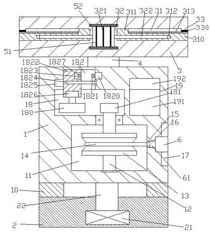
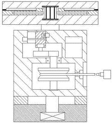
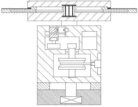
[0024] Such as Figure 1-Figure 4 As shown, a portable bridge device of the present invention includes a base 1 disposed above the base 2 and a top frame 3 disposed above the base 1, and a fourth driving machine 21 is provided at the inner bottom of the base 2, The top of the fourth driving machine 21 is connected with a rotating column 22, and the extended end of the top of the rotating column 22 penetrates the inner wall of the base 2 and is fixedly connected with the bottom end surface of the base 1. Between the base 1 and the base 2 The bearing 10 is fixedly arranged, the base body 1 is provided with a cavity 11, the base body 1 at the top of the cavity 11 is provided with a first cavity 18 and a second cavity 19, and the first cavity 18 The inner top wall is provided with a sliding groove 182, and the outer wall of the base body 1 on the right side of the cavity 11 is provided with a receiving groove 17, and a through groove 15 and a through groove 15 are arranged between...


PUM


Abstract

The invention discloses convenient bridge equipment. The convenient bridge equipment comprises a base body arranged above a base and a top frame arranged above the base body; a fourth driver is arranged at the bottom of the interior of the base; the top of the fourth driver is connected with a rotary column; an extension end on the top of the rotary column runs through the inner wall of the base and is fixedly connected with the bottom end plane of the base body; a bearing is fixedly arranged between the base body and the base; an accommodating cavity is formed in the base body; a first hollow groove and a second hollow groove are formed in the base body on the top of the accommodating cavity; a sliding groove is formed in the inner top wall of the first hollow groove; a fetching-taking groove is formed in the outer wall of the base body on the right side of the accommodating cavity; a through groove and a clamping groove are formed between the fetching-taking groove and the accommodating cavity; a rotary shaft which extends up and down is arranged in the accommodating cavity; an extension section on the top of the rotary shaft runs through the inner wall of the base body to extend into the first hollow groove; a first tooth-shaped wheel is fixedly arranged at the tail part of the rotary shaft in the first hollow groove; a reel is fixedly arranged on the rotary shaft in the accommodating cavity; a wire is wound in the reel; a sliding block is arranged in the sliding groove; the bottom of the sliding block extends into the first hollow groove; and a first driver is arranged in the bottom end plane of the sliding block. The convenient bridge equipment is simple in structure, convenient to operate, capable of collecting wires automatically, and high in safety.

Description

technical field [0001] The invention relates to the technical field of bridge facilities, in particular to a convenient bridge equipment. Background technique [0002] Electrified maintenance equipment is often used in the bridge maintenance process. However, in some bridge constructions, there are fewer preset power supply seats and they are all fixed. This makes it difficult to connect the power supply. In the prior art, one or more terminal boards are generally used to lengthen the connection to reach the ideal power supply plug-in length. Throw the power supply line on the ground, so that the power supply line is vulnerable to various accidental damages, such as people trampling on it, cars running over it, etc., resulting in damage to the outer insulation of the power supply line, resulting in a decrease in the life of the power supply line, and it is also very easy to induce electric shock accidents. In addition, the existing wiring boards are all connected to the mai...

Claims


Application Information

Patent Timeline
Patent Type & Authority Applications(China)
IPC IPC(8): H02G11/00H02G11/02H02S20/30H02S40/10
CPCH02G11/00H02G11/02H02S20/30H02S40/10Y02E10/50
Inventor 吕华
Owner 浦江净新环保科技有限公司
Why Eureka
Try Eureka