A Calibration Method for Peak Delay of Photoelastic Modulator

A photoelastic modulator and calibration method technology, which is applied in the direction of instruments, measuring devices, and measuring electrical variables, can solve the problems of large fluctuations in the light intensity of the calibration results and the inability to accurately calibrate the peak delay of the photoelastic modulator, and achieve calibration Accuracy improvement, the effect of improving accuracy

Active Publication Date: 2020-03-17
杭州诺驰生命科学有限公司
View PDF7 Cites 0 Cited by
  • Summary
  • Abstract
  • Description
  • Claims
  • Application Information

AI Technical Summary

Problems solved by technology

The Bessel function zeroing method cannot accurately calibrate the peak delay of the photoelastic modulator in the small-angle modulation state, and the calibration results are greatly affected by light intensity fluctuations

Method used


Image

  • A Calibration Method for Peak Delay of Photoelastic Modulator
  • A Calibration Method for Peak Delay of Photoelastic Modulator
  • A Calibration Method for Peak Delay of Photoelastic Modulator

Examples


Embodiment Construction

[0028] The present invention will be further described below in conjunction with the accompanying drawings and specific embodiments.

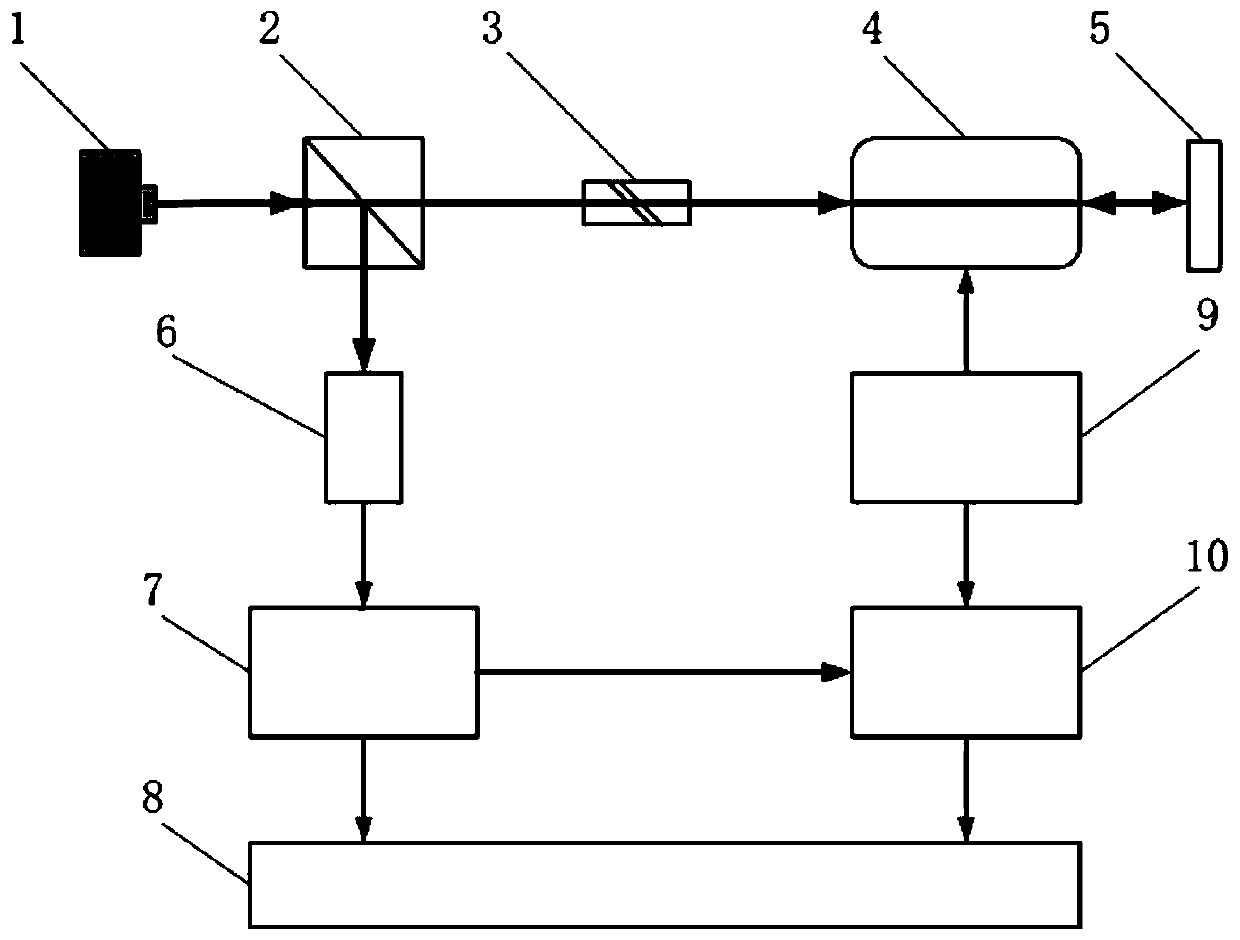
[0029] Such as figure 1 As shown, the calibration device mainly includes two parts: an optical measurement module and a signal processing module. The optical measurement module is composed of a laser 1, a polarization beam splitter 2, an eighth wave plate 3, a photoelastic modulator 4 and a mirror 5; the signal processing module is composed of a photodetector 6, a signal conditioner 7, a computer 8, an optical It is composed of a modulation driver 9 and a lock-in amplifier 10.

[0030] The positional relationship of each device in the above calibration device is as follows:

[0031] Along the advancing direction of the light beam emitted from the laser 1 are the polarization beam splitter 2 , the eighth wave plate 3 , the photoelastic modulator 4 and the mirror 5 in sequence. The first output terminal of the photoelastic modulation driver 9 ...


PUM


Abstract

The invention discloses a calibration method for peak retardation of a photoelastic modulator. A calibration device used by the calibration method comprises two parts of an optical measurement module and a signal processing module, wherein the optical measurement module is composed of a laser, a polarized beam splitter, an eighth-wave plate, the photoelastic modulator and a reflector, and modulation on the polarization state of incident light is completed altogether; and the signal processing module is composed of a photoelectric detector, a signal regulator, a phase-locked amplifier, the photoelastic modulation driver and a computer, and the peak retardation of the photoelastic modulator is obtained. The calibration method has high sensitivity when the photoelastic modulator works in a small-angle modulation state; as laser beams pass through the photoelastic modulator for two times successively, the calibration precision is improved by two times that of the traditional method; the calibration result is not influenced by incident light intensity fluctuation, the offset between the actual peak retardation of the photoelastic modulator caused by external environment and a set value can be corrected, and the precision of an atom spin precession detection result in an atom magnetometer can be improved.

Description

technical field [0001] The invention belongs to the technical field of polarization measurement, and in particular relates to a method for calibrating the peak delay of a photoelastic modulator, which can be widely used in the precise measurement of tiny rotation angles of the polarization direction of linearly polarized light using photoelastic modulators such as atomic magnetometers system. Background technique [0002] In recent years, with the rapid development of quantum precision measurement technology, atomic magnetometers based on atomic spin effects have received extensive attention and vigorous development due to their ultra-high theoretical accuracy. In the atomic magnetometer, the photoelastic modulation method is usually used to obtain the state information of atomic spin precession. The photoelastic modulator is a phase modulation device based on the photoelastic effect, which is mainly composed of isotropic optical materials and piezoelectric materials. The ...

Claims


Application Information

Patent Timeline
Patent Type & Authority Patents(China)
IPC IPC(8): G01D18/00G01R35/00
CPCG01D18/00G01R35/00
Inventor 全伟王清华房建成段利红
Owner 杭州诺驰生命科学有限公司
Why Eureka
Try Eureka