Shifting register unit and driving method, grid driving circuit, and display device thereof

A shift register unit and gate technology, which is applied in the fields of gate drive circuits, shift register units and their drivers, and display devices, can solve the problems of transistor device characteristic drift, potential rise, poor display, etc., to ensure output Accuracy, prevent characteristic drift, prevent poor display effect

Active Publication Date: 2017-09-05
BOE TECH GRP CO LTD +1
View PDF7 Cites 8 Cited by
  • Summary
  • Abstract
  • Description
  • Claims
  • Application Information

AI Technical Summary

Problems solved by technology

In the input stage (t1 stage), the input terminal INPUT and the second clock signal terminal input a high-level signal, and the first clock signal terminal CLK inputs a low-level signal, so that the pull-up node PU reaches a high-level potential; in the output stage (t2 stage), the input terminal INPUT and the second clock signal terminal CLKB input a low-level signal, the first clock signal terminal CLKA input a high-level signal, the pull-up transistor M3 is turned on, and the output terminal OUTPUT and the first clock signal terminal CLKA It is turned on to output a high-level signal. At the same time, under the bootstrap action of the capacitor C, the potential of the pull-up node PU will further increase, which will cause the device characteristics of the transistor connected to the pull-up node PU to drift, affecting the transistor The normal work, and then display bad

Method used


Image

  • Shifting register unit and driving method, grid driving circuit, and display device thereof
  • Shifting register unit and driving method, grid driving circuit, and display device thereof
  • Shifting register unit and driving method, grid driving circuit, and display device thereof

Examples


Embodiment Construction

[0045] Specific embodiments of the present invention will be described in detail below in conjunction with the accompanying drawings. It should be understood that the specific embodiments described here are only used to illustrate and explain the present invention, and are not intended to limit the present invention.

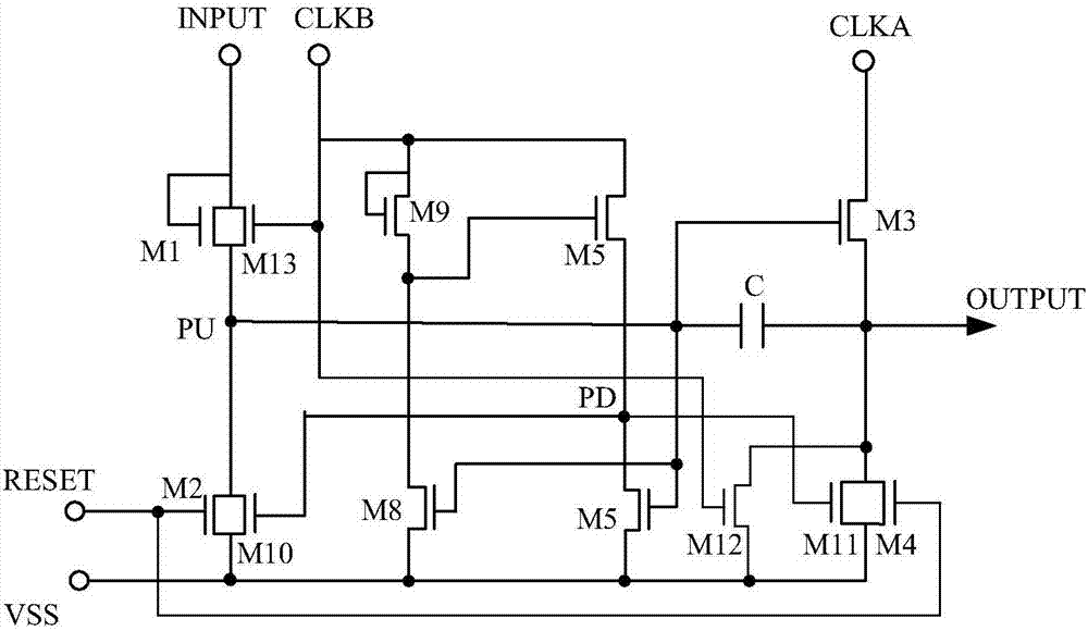
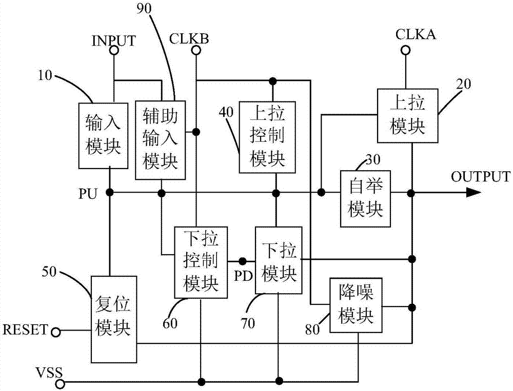
[0046] As an aspect of the present invention, a shift register unit is provided, such as image 3 As shown, the shift register unit includes an input module 10 , a pull-up module 20 , a bootstrap module 30 , a pull-up control module 40 and a reset module 50 . Wherein, the input module 10 is connected with the input terminal INPUT of the shift register unit and the pull-up node PU, and is used to charge the pull-up node PU when the input terminal INPUT of the shift register unit receives a valid signal, and the pull-up node PU is an input module 10 and the connection node between the bootstrap module 30. The pull-up module 20 is connected to the first clock sig...


PUM


Abstract

The invention provides a shifting register unit. The unit comprises an input module, a pull-up module, a bootstrap module, a pull-up control module and a reset module, wherein the input module is connected with an input end and a pull-up node of the shifting register unit and is used for charging for the pull-up node when the input end receives effective signals; the pull-up module is connected with a first clock signal end, an output end and the pull-up node and is used for enabling the output end to be conductively connected with the first clock signal end when the pull-up node reaches an effective potential; two ends of the bootstrap module are connected with the pull-up node and the output end respectively; the pull-up control module is connected with the pull-up node and is used for discharging for the pull-up node when the potential of the pull-up node is higher than the effective potential; the reset module is connected with a reset end, the pull-up node, the output end and an invalid signal end and is used for enabling the pull-up node and the output end to be conductively connected with the invalid signal end when the reset end receives the effective signals. The invention further provides a driving method, grid driving circuit, and display device of the shifting register unit. The shifting register unit can prevent transistor characteristic drifting which is caused by excessive high potential of the pull-up node.

Description

technical field [0001] The present invention relates to the field of display technology, in particular to a shift register unit, a driving method thereof, a gate driving circuit, and a display device. Background technique [0002] Gate Driver On Array (GOA for short) is a technology that integrates a gate driver circuit on an array substrate. The gate driver circuit includes a plurality of shift register units, and each shift register unit corresponds to a row of gates. Lines, multiple shift register units sequentially output scan signals. figure 1 is a schematic structural diagram of an existing shift register unit, which includes a plurality of transistors M1-M13 and a capacitor C, figure 2 for figure 1 The signal timing diagram when the shift register unit works. In the input stage (t1 stage), the input terminal INPUT and the second clock signal terminal input a high-level signal, and the first clock signal terminal CLK inputs a low-level signal, so that the pull-up n...

Claims


Application Information

Patent Timeline
Patent Type & Authority Applications(China)
IPC IPC(8): G09G3/20G11C19/28
CPCG09G3/20G11C19/28
Inventor 孙静刘金良孙松梅
Owner BOE TECH GRP CO LTD
Why Eureka
Try Eureka