A wall-mounted coat rack

A coat hanger and wall-attached technology, which is applied in the direction of hangers, clothing, applications, etc., can solve the problems of low utilization rate of hooks, inability to meet clothes, and reduce the number of clothes that can be hung, so as to improve the support limit effect and occupy space Small, the effect of improving availability

Active Publication Date: 2018-06-29
HAIMEN MAOFA ART DESIGN CO LTD
View PDF5 Cites 0 Cited by
  • Summary
  • Abstract
  • Description
  • Claims
  • Application Information

AI Technical Summary

Problems solved by technology

[0003] 1. This kind of coat rack is generally placed at the door or in the corner of the room, so that the coat rack is located in the area near the corner, and there is actually no space to hang clothes, so the hook on the coat rack The utilization rate is relatively low, which reduces the number of clothes that can be hung;
[0004] 2. The height of this coat rack cannot be adjusted, not only cannot meet the height requirements of different heights for the coat rack, but also cannot meet the needs of people to hang clothes of different heights according to different seasons

Method used


Image

  • A wall-mounted coat rack
  • A wall-mounted coat rack
  • A wall-mounted coat rack

Examples


Embodiment 1

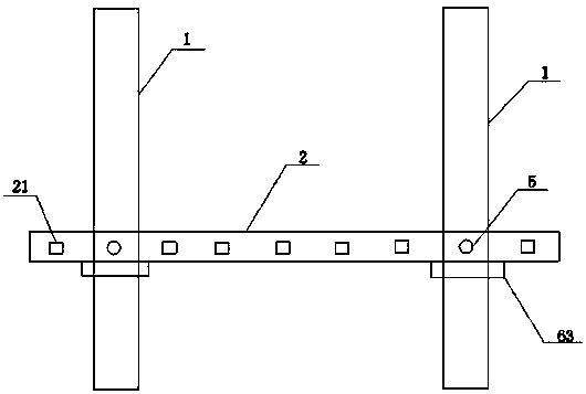
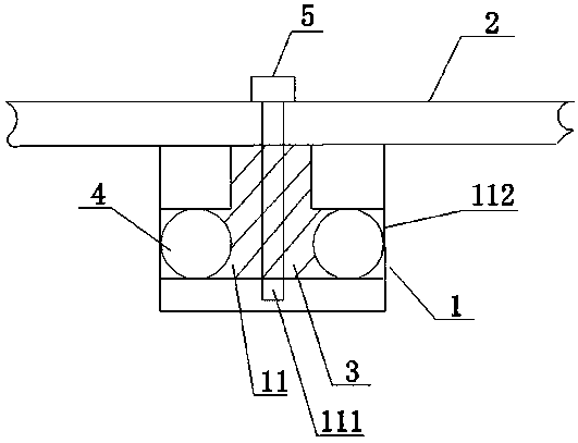
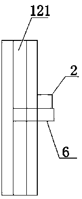
[0019] Such as Figure 1~Figure 4 As shown, the present invention provides a wall-mounted coat rack, comprising two longitudinal fixing frames 1 fixed on the wall and a horizontal clothes rail 2 connected to the two fixing frames 1, the clothes rail 2 Two protruding blocks 3 are arranged on it, and grooves 11 are arranged longitudinally on the fixed frame 1, and the two protruding blocks 3 are respectively fitted in the two grooves 11 and can move up and down in the grooves 11. The bottom surface of the groove 11 is provided with a longitudinal bayonet groove 111, and the bayonet 5 passes through the clothes hanger 2 and the protruding block 3 to fit in the bayonet groove 111, and the two ends of the fixed frame 1 are provided with longitudinal bayonet grooves. The positioning opening 121, the clamping block 62 is fixed on the fixed frame 1 through the two clamping openings 121, the clamping block 62 is connected with the limiting block 63 for limiting the clothes hanging rod ...

Embodiment 2

[0021] First, adjust the clothes rail 2 to a certain height according to the needs of the user, then insert and fix the bayonet 5 through the clothes rail 2 and the protruding block 3 into the bayonet groove 111, and then pass the bayonet 62 through the two bayonets. The position opening 121 is fixed on the fixed frame 1, and at this moment, the limit block 63 is just positioned at the bottom of the clothes hanger 2, and acts as a limit and fixation to the clothes hanger 2.


PUM


Abstract

The invention discloses a wall-attached coat rack The coat rack comprises two longitudinal fixing brackets fixed to the wall and a transverse hanging bar connected with the two fixing brackets. Two protruding blocks are arranged on the hanging bar, grooves are formed in the fixing brackets lengthwise, the two protruding blocks are matched in the two grooves respectively and capable of vertically moving in the grooves, a lengthwise bayonet slot is formed in the bottom surface of each groove, and each bayonet penetrates the hanging bar and the protruding block to be matched in each bayonet slot. According to the coat rack, the structure design of being attached to the wall is adopted, the occupation space is little, each hook of the coat rack can play a role in hanging clothes, the problems of blind zones and the low hook utilization of traditional coat racks are solved, and the height of the hanging bar can be adjusted as needed, so that the hanging height demands of populations with different heights are adapted, and people's requirements of different clothes hanging height according to different seasons are satisfied.

Description

technical field [0001] The invention relates to the field of living and home furnishing, in particular to a wall-mounted coat rack. Background technique [0002] Most of the existing household coat racks are relatively simple in structure, and are mainly vertical coat racks composed of bases, connecting columns and hooks. This coat rack has the following two disadvantages in actual use: [0003] 1. This kind of coat rack is generally placed at the door or in the corner of the room, so that the coat rack is located in the area near the corner, and there is actually no space to hang clothes, so the hook on the coat rack The utilization rate is relatively low, which reduces the number of clothes that can be hung; [0004] 2, the height of this coat rack cannot be adjusted, not only can not adapt to the height requirement of different heights for the coat rack, but also can not meet the needs of people hanging clothes of different heights according to the seasons. Contents of...

Claims


Application Information

Patent Timeline
Patent Type & Authority Patents(China)
IPC IPC(8): A47G25/06A47G25/10
CPCA47G25/06A47G25/10
Inventor 王趁红李允
Owner HAIMEN MAOFA ART DESIGN CO LTD
Why Eureka
Try Eureka