Machine tool buffering mechanism for motor shaft machining

A buffer mechanism and motor shaft technology, which is applied in metal processing machinery parts, metal processing equipment, manufacturing tools, etc., can solve the problem that the overall structure of the fixed motor shaft is not stable enough, so as to avoid debris flying around, improve stability, and improve stability. The effect of the support limit effect

Pending Publication Date: 2022-01-21
舒城久联精密机械有限公司
View PDF9 Cites 0 Cited by
  • Summary
  • Abstract
  • Description
  • Claims
  • Application Information

AI Technical Summary

Problems solved by technology

[0003] After searching, the Chinese patent application number is CN201911251837.2, which discloses a machine tool base with a vibration damping and buffering mechanism, including a main body of the machine base. A lower horizontal support plate is provided under the fixed bottom plate of the main body of the machine base. Outrigger devices are fixed on the edge of the horizontal support plate; multiple lower through holes are formed on the edge of the lower horizontal support plate, and multiple upper through holes are formed on the edge of the fixed bottom plate of the machine base body, but the above technical solution Since there is no corresponding mechanism that can keep the installation platform stable when it moves and stops, there is still friction between the installation platform and the wear-resistant lubrication plate when it moves, resulting in the fixing of the motor shaft when the installation platform moves. The overall structure is not stable enough

Method used


Image

  • Machine tool buffering mechanism for motor shaft machining
  • Machine tool buffering mechanism for motor shaft machining
  • Machine tool buffering mechanism for motor shaft machining

Examples


Embodiment 1

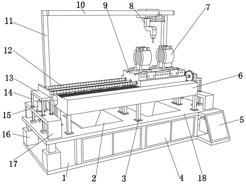
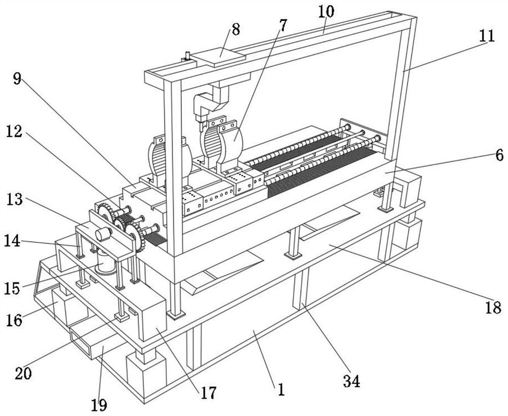
[0035] A machine tool buffer mechanism for motor shaft processing, such as Figure 1-8As shown, including the base plate 1, the outer wall of the top of the base plate 1 is fixed with a plurality of second support columns 34 by screws, the outer wall of the top of the second support column 34 is fixed with a support plate 18, and the outer wall of the top of the support plate 18 is fixed by screws. A first support column 3, the outer wall of the top of the first support column 3 is fixed with a set of mounting table 6 by screws, the outer wall of the top of the mounting table 6 is provided with a processing table 9, and the outer wall of one side of the processing table 9 is provided with a group of circular through holes. The inner wall of the through hole is provided with an internally threaded sleeve 35, and the inner wall of the internally threaded sleeve 35 is threadedly connected with an electric screw rod 12. The staff can control the electric screw rod 12 through the co...

Embodiment 2

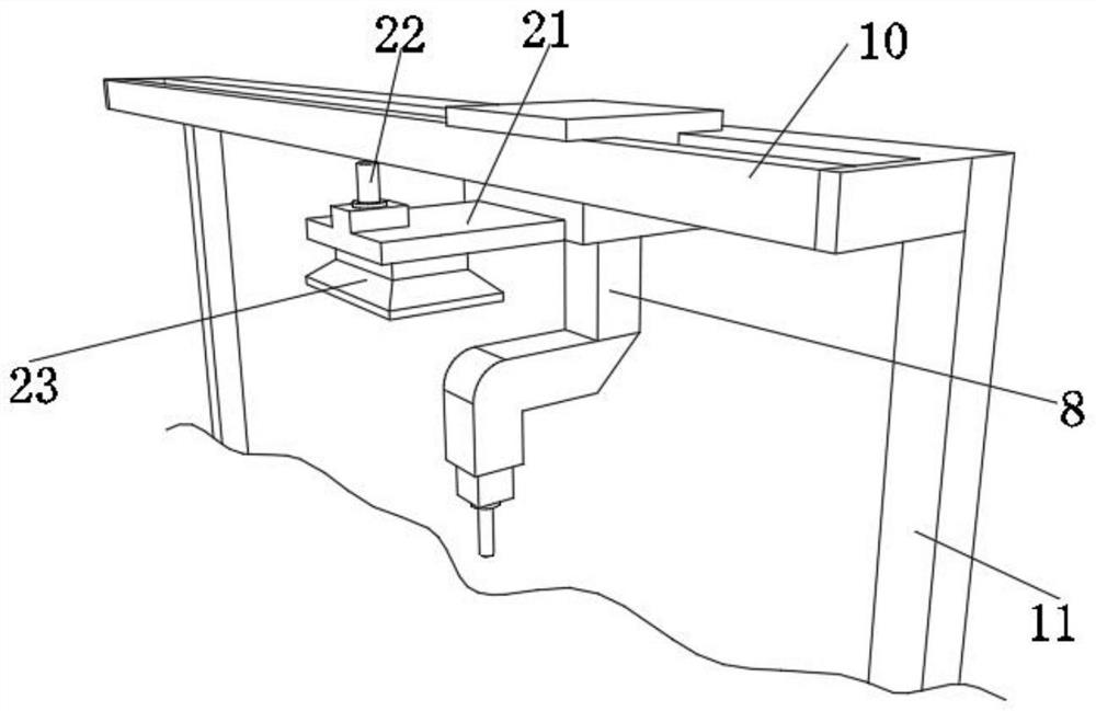
[0044] A machine tool buffer mechanism for motor shaft processing, such as figure 1 , image 3 As shown, in order to avoid debris flying randomly when processing the motor shaft; this embodiment makes the following improvements on the basis of Embodiment 1: the outer wall of one side of the processing manipulator 8 is fixed with a connecting plate 21 by screws, and the outer wall of the top of the connecting plate 21 passes through The screw is fixed with an electric control water valve 22, and the outer wall of the bottom of the connecting plate 21 is fixed with a water spray plate 23, and the electric control water valve 22 is electrically connected with the control panel 5; During the hole cutting process, a large amount of metal debris will be generated. The staff will connect the electric control water valve 22 with the outer wall water pump through the pipeline, and the control panel 5 can control the electric control water valve 22 to open. 22 Inject water flow into th...


PUM


Abstract

The invention discloses a machine tool buffering mechanism for motor shaft machining, and relates to the technical field of machine tool equipment. The problem that when an installation platform moves, the overall structure for fixing a motor shaft is not stable enough is solved. The machine tool buffering mechanism specifically comprises a bottom plate, a plurality of second supporting columns are fixed to the outer wall of the top of the bottom plate, a supporting plate is fixed to the outer walls of the tops of the second supporting columns, a plurality of first supporting columns are fixed to the outer wall of the top of the supporting plate, and a set of mounting tables are fixed to the outer walls of the tops of the first supporting columns. By arranging a lifting mechanisms, when a control panel is about to control an electric lead screw to drive a machining table to move back and forth, the control panel firstly controls the lifting mechanisms located on the two sides of the electric lead screw to push the electric lead screw to move upwards by a set distance, and the control panel can control the lifting mechanism to reset so that the whole machining table can be more stable when the machining manipulator machines the motor shaft clamped and fixed on the machining table.

Description

technical field [0001] The invention relates to the technical field of machine tools, in particular to a machine tool buffer mechanism for motor shaft processing. Background technique [0002] The motor shaft is an important part of the motor. As the link of electromechanical energy conversion between the motor and the equipment, it supports the rotating parts, transmits the torque and determines the relative position of the rotating parts to the stator. The processing quality of the motor shaft has a great influence on the performance of the motor. The important influence is that the motor shaft is generally made of carbon steel. Generally, it needs to be processed by turning, milling, drilling, etc. When processing the motor shaft, it is necessary to ensure that the overall processing machine tool tends to be stable. Only the processing machine tool Only by maintaining stability during processing can the accuracy of motor shaft processing be guaranteed. [0003] After ret...

Claims


Application Information

Patent Timeline
Patent Type & Authority Applications(China)
IPC IPC(8): B23Q1/26B23Q1/72B23Q11/00
CPCB23Q1/26B23Q1/72B23Q11/0042B23Q11/0032
Inventor 宋浩
Owner 舒城久联精密机械有限公司
Why Eureka
Try Eureka