
Centrifugal atomizer

A technology of centrifugal atomization and atomization disk, which is applied in the field of electrical appliances, can solve the problems of large fog particles, large vibration of the atomization disk, and the inability to handle backflow water well, so as to increase the contact area, improve the quality of use, and prevent fogging. better effect

Inactive Publication Date: 2017-09-08
GUANGDONG ZHAOQING DETON
View PDF7 Cites 3 Cited by
  • Summary
  • Abstract
  • Description
  • Claims
  • Application Information

AI Technical Summary

Problems solved by technology

[0004] 1. The return water cannot be handled well. Although a water collection tray is installed, part of the water mist will condense into water droplets and fall into the water collection tray to be collected, but there are still some water mist condensed into water droplets on the outer wall of the water collection tray. , and because these water droplets will not be blown by the wind blown by the blowing device behind the atomizer, they will fall to the ground, there are shortcomings such as fog accumulation and dripping on the outer edge of the water collection tray, and the water droplets may flow back along the return pipe to the Leakage of electrical components caused by the inside of the column
[0005] 2. The atomizing motor is installed inside the water trap, which has poor heat dissipation conditions, high temperature and short life.
[0006] 3. The vibration of the atomizing disc is large, resulting in large fog particles, serious flying water, and poor atomization effect
[0007] 4. The safety cover is easy to fly and drip
[0008] The above four shortcomings have greatly affected the sales and promotion of centrifugal atomizers

Method used


Image

  • Centrifugal atomizer
  • Centrifugal atomizer
  • Centrifugal atomizer

Examples


Embodiment Construction

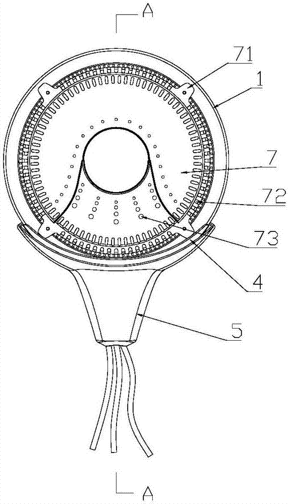
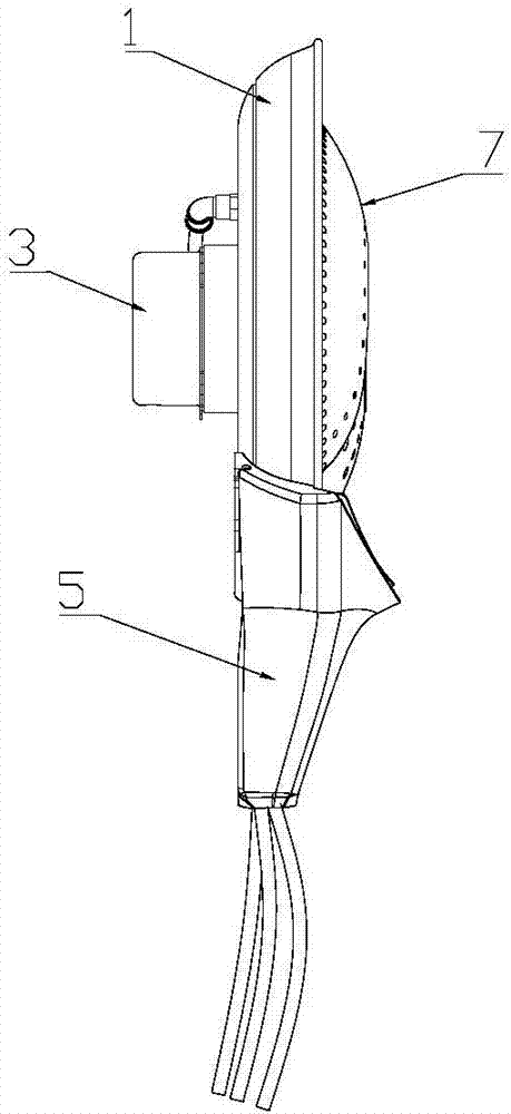
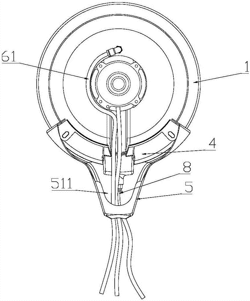
[0036] like Figure 1-Figure 6 As shown, the present invention provides a centrifugal atomizer, comprising a water collecting tray 1, an atomizing tray 2, a motor 3 for driving the atomizing tray 2 to rotate, a water supply device 6 for injecting water into the atomizing tray 2, a collecting The water tray 4 and the guide cover 5 that guides the wind to blow upward, the atomization tray 2 is located in the water collection tray 1, and the circumference of the water collection tray 1 is provided with a The atomization part 11 where the water phase collides, the water collecting pan 4 is located under the water collecting pan 1 , and the flow guide cover 5 is arranged under the water collecting pan 4 . Start the motor 3, the atomizing disc 2 rotates at high speed, the water from the water supply device falls on the atomizing disc 2, and under the action of the centrifugal force generated by the high-speed rotation of the atomizing disc 2, it diverges and accelerates along the in...


PUM

PropertyMeasurementUnit
Widthaaaaaaaaaa

Abstract

The invention provides a centrifugal atomizer. The centrifugal atomizer comprises a water collecting tray, an atomizing tray, a motor, a water supply device, a water receiving tray and an air guide sleeve, wherein the motor is used for driving the atomizing tray to rotate; the water supply device is used for feeding water to the atomizing tray; the air guide sleeve is used for guiding the air to be blown out upwards; the atomizing tray is positioned inside the water collecting tray; an atomizing part having collision with water which is ejected at a high speed from the periphery of the atomizing tray is arranged on the circumference of the water collecting tray; the water receiving tray is positioned below the water collecting tray; and the air guide sleeve is arranged below the water receiving tray. The atomizer provided by the invention can prevent the water mist formed by atomization from being condensed into water droplets on the outer wall of the water receiving tray so that no water droplets drop on the ground and water accumulation is prevented.

Description

technical field [0001] The invention relates to a centrifugal atomizer, which belongs to the technical field of electric appliances. Background technique [0002] The centrifugal atomizer is composed of an atomizing motor, a water collecting pan, an atomizing pan, and a water collecting pan. Generally, the atomizer is used in conjunction with the water supply system and blower such as a fan or fan. The water supply system is at the bottom of the atomizer, and the blower is behind the atomizer. Start the motor, the atomizing disc rotates at high speed, the water from the water supply device falls on the atomizing disc, under the action of the centrifugal force generated by the high-speed rotation of the atomizing disc, it diverges and accelerates along the inner surface of the atomizing disc, and flows from the edge of the atomizing disc It shoots rapidly on the water collecting tray, and after the collision, a fine water mist is formed, and the water mist is blown away by t...

Claims


Application Information

Patent Timeline
IPC IPC(8): B05B3/02B05B15/04B05B12/08B05B13/02B05B15/00
CPCB05B3/02B05B12/082B05B13/0278B05B15/00
Inventor 李俞王华
Owner GUANGDONG ZHAOQING DETON
Learn More