Novel high-strength packaging box

A high-strength, new technology, applied in packaging, transportation and packaging, rigid containers, etc., can solve the problems of difficult handling, inconvenient packaging of precision instruments, etc., to achieve the effect of convenient handling

Active Publication Date: 2017-09-08
苏州宏创包装科技有限公司
View PDF8 Cites 2 Cited by
  • Summary
  • Abstract
  • Description
  • Claims
  • Application Information

AI Technical Summary

Problems solved by technology

[0005] In order to solve the problem that the existing precision instruments are inconvenient to pack into packing boxes and difficult to carry, the purpose of this invention is to provide a new type of high-strength packing box, which has the advantages of convenient placement and transportation of precision instruments

Method used


Image

  • Novel high-strength packaging box
  • Novel high-strength packaging box
  • Novel high-strength packaging box

Examples


Embodiment 1

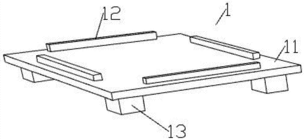
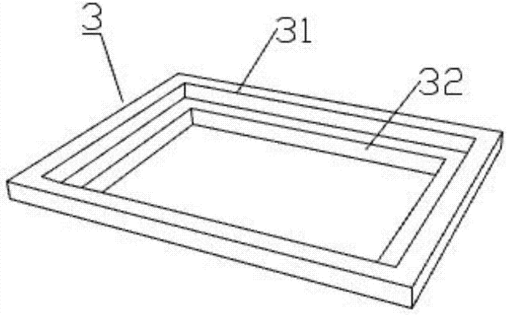
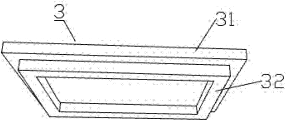
[0034] Such as Figure 1-6 As shown, a novel high-strength packing case of the present invention comprises a case base 1, a shock absorbing pad 3 placed on the case base 1 and a case cover 2 placed on the case base 1, the shock absorbing pad 3 and the case cover 2 They are all in contact with the box base 1, and the shock absorbing pad 3 is located in the box cover 2. The box base 1 includes a rectangular bottom plate 11, a limit block 12 fixed on the bottom plate 11 parallel to the four sides of the bottom plate 11 and fixed on the bottom of the bottom plate 11. The bearing 13 on the four corners, the shock absorber 3 includes a first square ring foam board 31 and a second square ring foam board 32 integrally formed, the first square ring foam board 31 is placed on the base plate 11, the second square ring foam board 31 The square ring foam board 32 is placed on the limit block 12, the case cover 2 is an open box body, the opening of the case cover 2 faces downward, the limit...

Embodiment 2

[0036] Such as Figure 7 As shown, Example 2 improves the structure of the box base 1 on the basis of Example 1. The box base 1 also includes two parallel support plates 14, and the two ends of the support plates 14 are fixed on the bottom of the two supports 13. The setting of the support plate 14 can be placed more stably when the present invention is stacked up and down, preventing the present invention from falling down and damaging precision instruments because a support 13 is not put in place.

Embodiment 3

[0038] Such as Figure 8 As shown, embodiment 3 continues to improve the structure of the box base 1 on the basis of embodiment 2, and the bottom plate 11 is also provided with a limit cardboard 15, which is a box body with open ends at both ends, and the limit cardboard 15 is fixed At the edge of the bottom plate 11 , the limiting cardboard 15 is located on the periphery of the box cover 2 . The setting of the limit cardboard 15 makes the placement of the case cover 2 more stable, and the case cover 2 is difficult to move between the limit cardboard 15 and the limit block 12 .


PUM


Abstract

The invention provides a novel high-strength packaging box and particularly relates to the technical field of precise instrument packaging. The novel high-strength packaging box comprises a box base, a shock pad arranged on the box base, and a box cover arranged on the box base. The shock pad and the box cover are in contact connection with the box base. The shock pad is located in the box cover. The box base comprises a rectangular bottom plate, limiting blocks which are fixed to the bottom plate and are parallel to the four edges of the bottom plate, and supports fixed to the four corners of the bottom of the bottom plate. The shock pad comprises a first square ring foam board and a second square ring foam board which are integrally formed. The first square ring foam board is arranged on the bottom plate. The second square ring foam board is arranged on the limiting blocks. The box cover is an open box body. An opening of the box cover faces downwards. The limiting blocks are located in the box cover. The box cover is in contact connection with the limiting blocks. The novel high-strength packaging box has the advantages that precise instruments can be placed conveniently and be carried by forklifts conveniently.

Description

technical field [0001] The invention belongs to the technical field of precision instrument packaging, and in particular relates to a novel high-strength packing box. Background technique [0002] When putting precision instruments into the packaging box, due to fear of impact and other reasons, care must be taken when putting them in, and it is not convenient to put them into the box. It is also not easy to carry after being put into the box and stacked in the warehouse, which wastes manpower, and the work efficiency is low. Now the packing boxes on the market can only have the shock absorption function for precision instruments, and there is no packing box that is easy to carry. [0003] The patented precision instrument packaging box (publication number: CN204896323U) discloses a precision instrument packaging box. The precision instrument packaging box includes an inner box body and an outer box body. The inner box body is a corrugated cardboard with a triangular or squa...

Claims


Application Information

Patent Timeline
Patent Type & Authority Applications(China)
IPC IPC(8): B65D19/26B65D19/44B65D19/38
CPCB65D19/0028B65D19/38B65D19/44B65D2519/00273B65D2519/00338B65D2519/00711B65D2519/00815
Inventor 张剑英
Owner 苏州宏创包装科技有限公司
Why Eureka
Try Eureka