
Industrial dewaterer

A dehydrator, industrial technology, used in textile processing machine accessories, textiles and papermaking, liquid/gas/vapor removal by centrifugal force, etc., can solve the problems of subsequent steps, machine damage, etc., to reduce discomfort and increase service life. The effect of surface and high degree of automation

Inactive Publication Date: 2017-09-08
泰州国鑫机械制造有限公司
View PDF0 Cites 0 Cited by
  • Summary
  • Abstract
  • Description
  • Claims
  • Application Information

AI Technical Summary

Problems solved by technology

[0003] The purpose of the present invention is to provide an industrial dehydrator to solve the problem that the industrial dehydrator proposed in the above background technology usually has a simple structure and can be directly centrifuged to achieve the effect of dehydration. Such a dehydrator will affect the subsequent steps after dehydration, and it is easy to cause The problem of machine damage

Method used


Image

  • Industrial dewaterer
  • Industrial dewaterer
  • Industrial dewaterer

Examples


Embodiment Construction

[0015] The following will clearly and completely describe the technical solutions in the embodiments of the present invention with reference to the accompanying drawings in the embodiments of the present invention. Obviously, the described embodiments are only some, not all, embodiments of the present invention. Based on the embodiments of the present invention, all other embodiments obtained by persons of ordinary skill in the art without making creative efforts belong to the protection scope of the present invention.

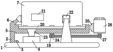
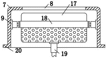
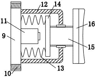
[0016] see Figure 1-4 , the present invention provides a technical solution: an industrial dehydrator, including a base 1, three sets of legs 2 are connected to the top of the base 1, and a mounting plate 3 is connected to the bottom of the legs 2, and the mounting plate 3 is connected to the base 1 through bolts. The top is connected, the top of the base 1 is installed with a water collection tank 4, the top of the leg 2 is connected with a support plate 5, ...


PUM


Abstract

The invention discloses an industrial dehydrator in the field of dehydrator technology, comprising a base, three sets of outriggers are connected to the top of the base, and a mounting plate is connected to the bottom of the outriggers, and the mounting plate is connected to the top of the base through bolts. connected, the top of the base is equipped with a water collection tank, the top of the legs is connected with a support plate, the top of the support plate is connected with three sets of brackets, and the top of the support plate is connected with a dehydration shell through three sets of brackets, so There is a feeding trough on the top of the dehydration shell, the left and right side walls of the inner cavity of the dehydration shell are connected with connecting seats, and the upper and lower sides of the connecting seat are provided with screw holes. The setting is convenient for controlling the speed of the dehydrator, reducing the discomfort of the motor starting to rotate and increasing the speed, and increasing the service life of the device. The electromagnet is used as the power source of the friction plate, and the degree of automation is high.

Description

technical field [0001] The invention relates to the technical field of dehydrators, in particular to an industrial dehydrator. Background technique [0002] In the production and processing of cloth, the cloth needs to be dyed, dried and other steps, so it is necessary to dehydrate the wet cloth. The industrial dehydrator usually has a simple structure and can be directly centrifuged to achieve the effect of dehydration. Such a dehydrator is very useful for the subsequent steps after dehydration. cause impact, and it is easy to cause damage to the machine. For this reason, we propose an industrial dehydrator. Contents of the invention [0003] The purpose of the present invention is to provide an industrial dehydrator to solve the problem that the industrial dehydrator proposed in the above background technology usually has a simple structure and can be directly centrifuged to achieve the effect of dehydration. Such a dehydrator will affect the subsequent steps after dehyd...

Claims


Application Information

Patent Timeline
Patent Type & Authority Applications(China)
IPC IPC(8): D06B15/10D06B23/00
CPCD06B15/10D06B23/00
Inventor 袁祥李涵雄周旺平刘云平
Owner 泰州国鑫机械制造有限公司
Learn More