
Roadbed detecting device for roads

A detection device and roadbed technology, which is applied in the field of foundation soil survey, infrastructure engineering, construction, etc., can solve the problems of insufficient detection results of road detection equipment, inconvenient transportation and operation of inspection equipment, etc., to increase structural diversity , Improve practicability, optimize the effect of testing procedures

Inactive Publication Date: 2017-09-12
西藏灵芝草建设咨询集团有限公司
View PDF6 Cites 6 Cited by
  • Summary
  • Abstract
  • Description
  • Claims
  • Application Information

AI Technical Summary

Problems solved by technology

[0007] The present invention mainly provides a subgrade detection device for roads, which is used to solve the technical problems raised in the above technical background, that the detection results of existing road detection equipment are not rigorous enough, and the inspection equipment is inconvenient to transport and operate.

Method used


Image

  • Roadbed detecting device for roads
  • Roadbed detecting device for roads
  • Roadbed detecting device for roads

Examples


Embodiment 1

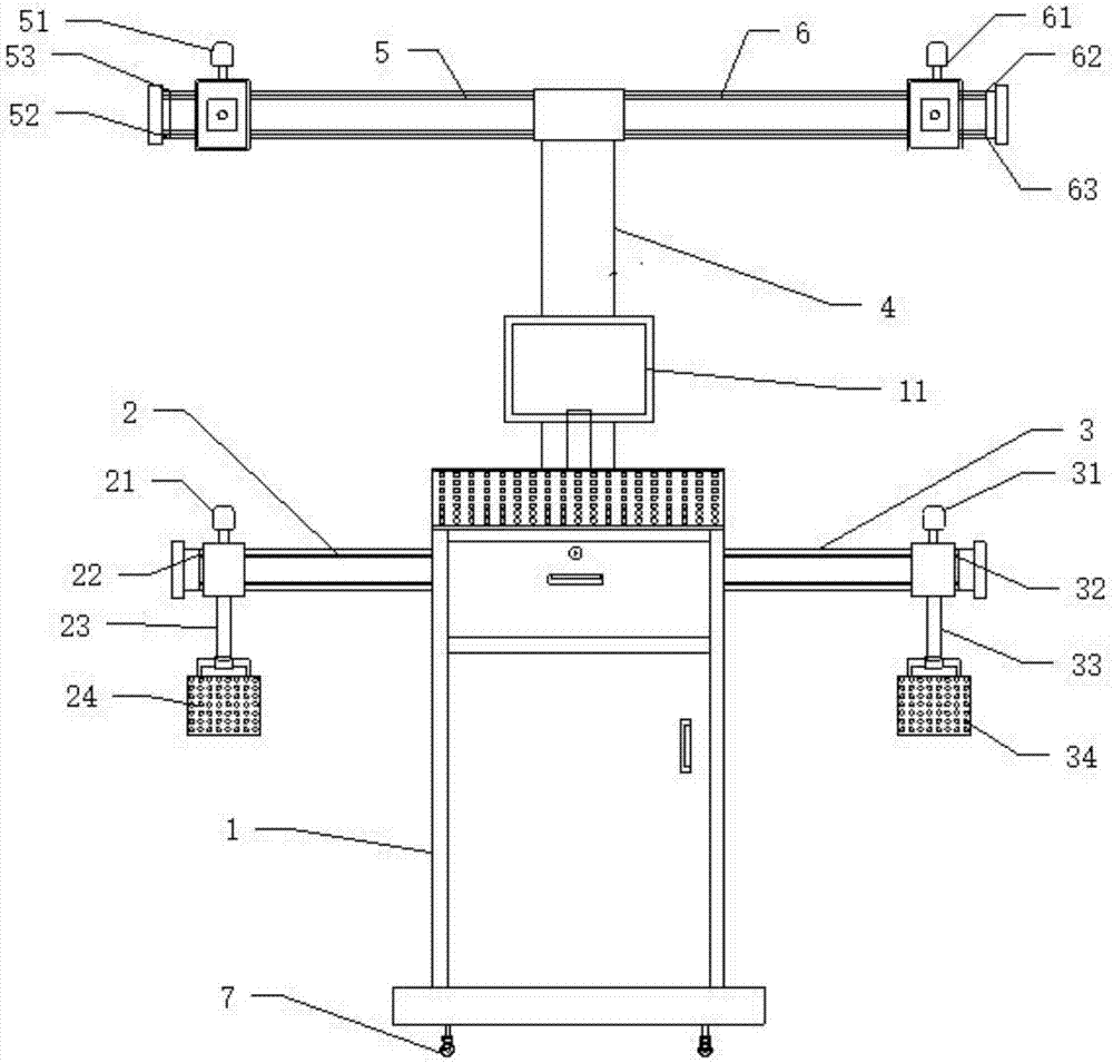
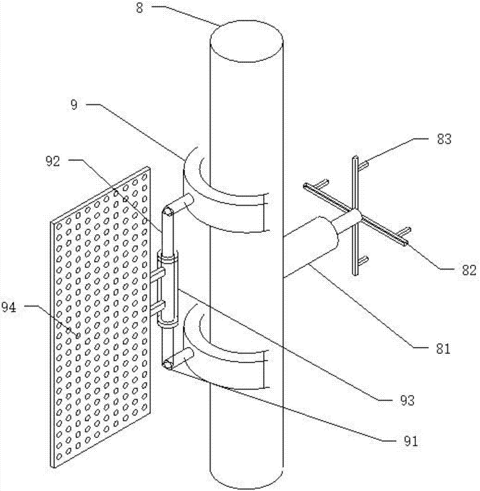
[0058] Embodiment 1, when it is necessary to use the detection equipment for detection, the fixed column 8 can be fixed on the subgrade section to be detected, and the first slider 22, the second slider 32, and the third slider are controlled by the control panel. Block 52 and the fourth slide block 62 slide left and right respectively on the first track 2, the second track 3, the third track 5 and the fourth track 6 to adjust the first CCD sensor 24, the second CCD sensor 34, the first infrared ray After transmitter 54 and the second infrared transmitter 64 correspond to each other with signal receiver 94, after opening the transmitting switch of two infrared transmitters, described signal receiver 94 accepts the signal of infrared transmitter, and described signal receiver 94 will After the received data signals are sorted and analyzed, they are sent to two CCD sensors for processing. After the two CCD sensors analyze the received data, they are sent to the computer and displ...

Embodiment 2

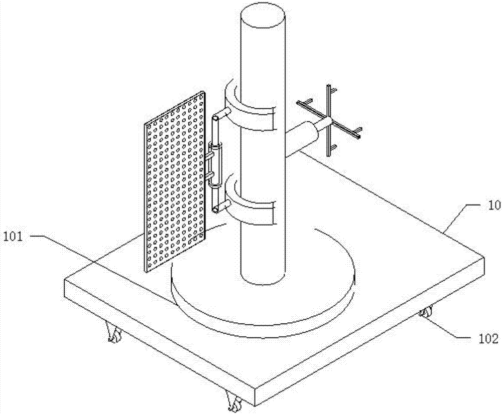
[0059] Embodiment 2, a turntable 101 can be fixed at the bottom of the support column 8, and the turntable 101 can be fixed on the end face of the movable plate 10, and the placement position can be selected according to the actual situation of the foundation, after the steps of the above-mentioned embodiment 1 , to perform device detection.


PUM


Abstract

The invention provides a roadbed detecting device for roads. The device comprises a main chassis; a computer display screen is fixed on the main chassis; a first rail is fixed on the left side of the main chassis; a first CCD sensor is slidingly mounted on the first rail; a second rail is fixed on the right side of the main chassis; a second CCD sensor is slidingly mounted on the second rail; the top end of the main chassis is connected with a rail module of an infrared emitter through a support rod; the rail module comprises a third rail and a fourth rail; a first infrared emitter is slidingly mounted on the third rail; a second infrared emitter is slidingly mounted on the fourth rail; signals emitted by the two infrared emitters can be received through a signal receiver and sent to the two CCD sensors; and the signal receiver is rotationally mounted on a fixed column. Compared with traditional roadbed detecting equipment, the device is more precise in detection, high in practicability and suitable for popularization and application.

Description

technical field [0001] The invention relates to a roadbed detection device, and specifically provides a roadbed detection device for roads. technical background [0002] Roadbed detection equipment is the main auxiliary equipment in road construction. Before road construction, it is necessary to use the roadbed detection device to detect the condition of the roadbed. [0003] In the process of road construction, due to the unevenness of the road subgrade, the difficulty of construction is often increased. At the same time, phenomena such as road deflection will also cause construction difficulties. Based on this, it is necessary to develop a detection equipment to meet the detection of road conditions. , and then carry out construction according to the detected subgrade conditions, thereby reducing construction difficulty and ensuring construction accuracy. [0004] In the existing detection equipment, the detection level is limited and the measurement accuracy is not enoug...

Claims


Application Information

Patent Timeline
Patent Type & Authority Applications(China)
IPC IPC(8): E02D1/00
CPCE02D1/00
Inventor 不公告发明人
Owner 西藏灵芝草建设咨询集团有限公司
Learn More