Eureka AIR delivers breakthrough ideas for toughest innovation challenges, trusted by R&D personnel around the world.

Interconnect structure and method

A semiconductor and conductive interconnection technology, which is applied in semiconductor/solid-state device manufacturing, semiconductor devices, semiconductor/solid-state device components, etc., can solve problems such as unsatisfactory use and unsatisfactory materials

Active Publication Date: 2017-09-12
TAIWAN SEMICON MFG CO LTD
View PDF6 Cites 1 Cited by
  • Summary
  • Abstract
  • Description
  • Claims
  • Application Information

AI Technical Summary

Problems solved by technology

[0003] However, materials currently considered or used as low-K dielectric materials are not ideal
In particular, when selecting a material based on its K value, and especially based on the material's low K value, other properties, such as hardness or length, may not be ideal for use in semiconductor manufacturing processes

Method used


Image

  • Interconnect structure and method
  • Interconnect structure and method
  • Interconnect structure and method

Examples


Embodiment Construction

[0014] The following disclosure provides many different embodiments or examples for realizing different functions of the present invention. Specific examples of components and arrangements are described below in order to briefly illustrate the present disclosure. Of course these are examples only and are not intended to be limiting. For example, in the ensuing description, a first functional element formed on or over a second functional element may include embodiments in which the first and second functional elements form direct contact, and may also include embodiments in which additional functional elements are formed on the first functional element. and the second functional part, so that the first and second functional parts may not have direct contact. In addition, this disclosure may repeat numbers and / or letters in various examples. This repetition is for simplicity and clarity and does not in itself indicate a relationship between the various embodiments and / or confi...


PUM


Abstract

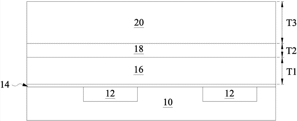
A device, structure, and method are provided whereby an insert layer is utilized to provide additional support for surrounding dielectric layers. The insert layer may be applied between two dielectric layers. Once formed, trenches and vias are formed within the composite layers, and the insert layer will help to provide support that will limit or eliminate undesired bending or other structural motions that could hamper subsequent process steps, such as filling the trenches and vias with conductive material.

Description

technical field [0001] Embodiments of the present invention relate to the field of semiconductors, and more particularly, to an interconnect structure and a manufacturing method thereof. Background technique [0002] In the current miniaturized semiconductor device process, it is necessary to use low-K value materials as intermetal dielectric layers and / or interlayer dielectric layers between conductive interconnects to reduce resistance and capacitance due to capacitive effects in signal propagation (RC) Delay. Because of this, the lower the dielectric constant of the dielectric, the lower the parasitic capacitance of adjacent conductive lines and the RC delay of the integrated circuit (IC). [0003] However, materials currently considered or used as low-K dielectric materials are not ideal. In particular, when a material is selected based on the K value, and especially based on the material's low K value, other properties, such as hardness or length, may not be ideal for...

Claims


Application Information

Patent Timeline
IPC IPC(8): H01L23/528H01L21/60
CPCH01L23/528H01L24/27H01L23/53295H01L21/823431H01L21/823475H01L21/845H01L29/66545H01L21/76829H01L29/0847H01L2221/1047H01L21/76807H01L21/76826H01L23/5226H01L23/53238H01L21/76802H01L21/76816H01L21/76831H01L21/76841H01L21/76877H01L21/76895H01L21/76835H01L21/76801H01L21/76838H01L21/7684H01L21/76843H01L21/76879H01L23/5283H01L29/7851
Inventor 周家政纪志坚柯忠祁张耀仁高承远郭凯翔施伯铮李资良阮俊亿
Owner TAIWAN SEMICON MFG CO LTD
Why Eureka
Eureka Blog
Learn More