Dust removal device for detection equipment
A dust removal device and detection equipment technology, applied in cleaning methods and appliances, cleaning methods using tools, cleaning methods using gas flow, etc., can solve the problems of slow dust removal speed, poor dust removal effect, and time-consuming, etc., to achieve dust removal Fast speed, high work efficiency and good dust removal effect
- Summary
- Abstract
- Description
- Claims
- Application Information
AI Technical Summary
Problems solved by technology
Method used
Image

Examples
Embodiment 1
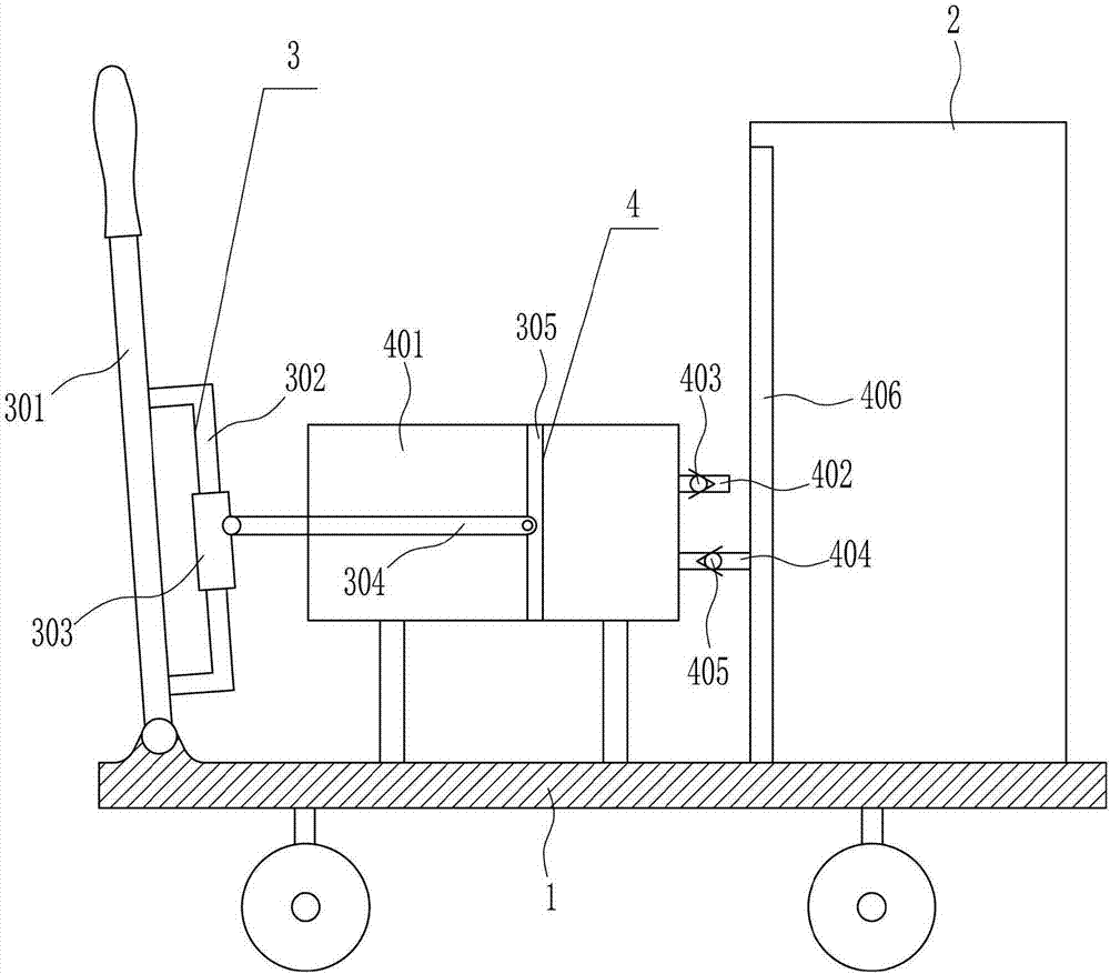
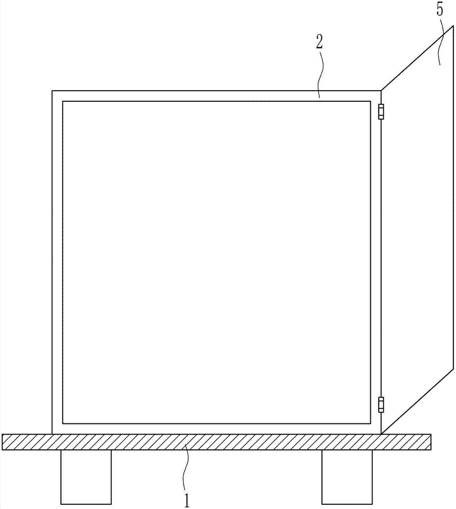
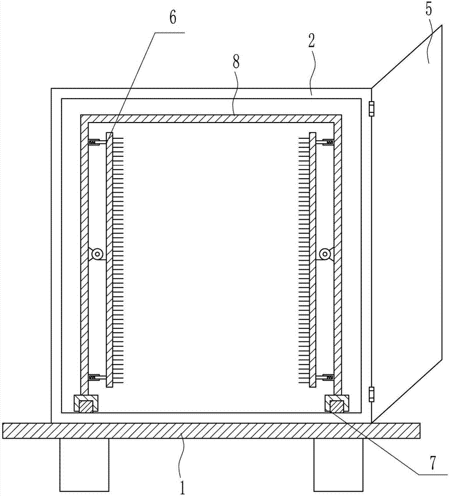
[0037] A dust removal device for testing equipment, such as Figure 1-7 As shown, it includes a trolley 1, a box body 2, a box door 5, a driving mechanism 3 and a dust removal mechanism 4. The top right side of the top of the trolley 1 is welded with a box body 2, and the right rear side of the box body 2 is provided with a box door 5. The box door 5 is connected to the right rear side of the box body 2 through a hinge, the driving mechanism 3 is provided on the top left side of the cart 1, and the dust removal mechanism 4 is arranged in the middle of the top of the cart 1, and the dust removal parts on the dust removal mechanism 4 are located in the box body 2 On the left side, the drive components on the drive mechanism 3 cooperate with the dust removal mechanism 4 .
Embodiment 2
[0039] A dust removal device for testing equipment, such as Figure 1-7 As shown, it includes a trolley 1, a box body 2, a box door 5, a driving mechanism 3 and a dust removal mechanism 4. The top right side of the top of the trolley 1 is welded with a box body 2, and the right rear side of the box body 2 is provided with a box door 5. The box door 5 is connected to the right rear side of the box body 2 through a hinge, the driving mechanism 3 is provided on the top left side of the cart 1, and the dust removal mechanism 4 is arranged in the middle of the top of the cart 1, and the dust removal parts on the dust removal mechanism 4 are located in the box body 2 On the left side, the drive components on the drive mechanism 3 cooperate with the dust removal mechanism 4 .
[0040] The driving mechanism 3 includes a push rod 301, a connecting rod 302, a connecting block 303, a connecting rod 304 and a piston 305. The push rod 301 is connected with the top left side of the cart 1 b...
Embodiment 3
[0042] A dust removal device for testing equipment, such as Figure 1-7 As shown, it includes a trolley 1, a box body 2, a box door 5, a driving mechanism 3 and a dust removal mechanism 4. The top right side of the top of the trolley 1 is welded with a box body 2, and the right rear side of the box body 2 is provided with a box door 5. The box door 5 is connected to the right rear side of the box body 2 through a hinge, the driving mechanism 3 is provided on the top left side of the cart 1, and the dust removal mechanism 4 is arranged in the middle of the top of the cart 1, and the dust removal parts on the dust removal mechanism 4 are located in the box body 2 On the left side, the drive components on the drive mechanism 3 cooperate with the dust removal mechanism 4 .
[0043] The driving mechanism 3 includes a push rod 301, a connecting rod 302, a connecting block 303, a connecting rod 304 and a piston 305. The push rod 301 is connected with the top left side of the cart 1 b...
PUM
 Abstract
Description
Claims
Application Information
 - R&D
- Intellectual Property
- Life Sciences
- Materials
- Tech Scout
- Unparalleled Data Quality
- Higher Quality Content
- 60% Fewer Hallucinations
Browse by: Latest US Patents, China's latest patents, Technical Efficacy Thesaurus, Application Domain, Technology Topic, Popular Technical Reports.
© 2025 PatSnap. All rights reserved.Legal|Privacy policy|Modern Slavery Act Transparency Statement|Sitemap|About US| Contact US: help@patsnap.com