Self-locking control device for hoisting equipment

A control device and lifting equipment technology, applied in the direction of safety devices, transportation and packaging, load suspension components, etc., can solve problems such as easy slipping, hidden safety hazards, poor reliability, etc., and achieve improved safety in use, ingenious structure, The effect of convenient operation

Active Publication Date: 2017-09-15
河北战兴索具集团有限公司
View PDF5 Cites 3 Cited by
  • Summary
  • Abstract
  • Description
  • Claims
  • Application Information

AI Technical Summary

Problems solved by technology

At present, most of this type of equipment is equipped with reverse self-locking devices, but these self-locking devices are mostly primitive control structures, such as self-locking springs or ratchet pawls, etc. This structure is not only unreliable, but also inconvenient to operate, such as The commonly used ratchet and pawl structure needs to be shifted to complete self-locking or unlocking. Once it is misoperated, it may cause a major safety accident; although the self-locking spring can realize self-locking and unlocking without additional operations. Unlocking, but it is prone to slipping when working under heavy loads, and there are also major safety hazards

Method used


Image

  • Self-locking control device for hoisting equipment
  • Self-locking control device for hoisting equipment
  • Self-locking control device for hoisting equipment

Examples


Embodiment Construction

[0012] The specific implementation manners of the present invention will be described in further detail below in conjunction with the accompanying drawings.

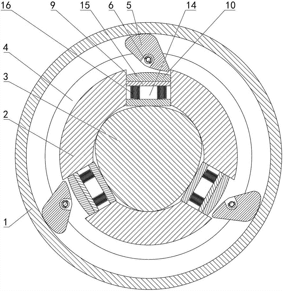
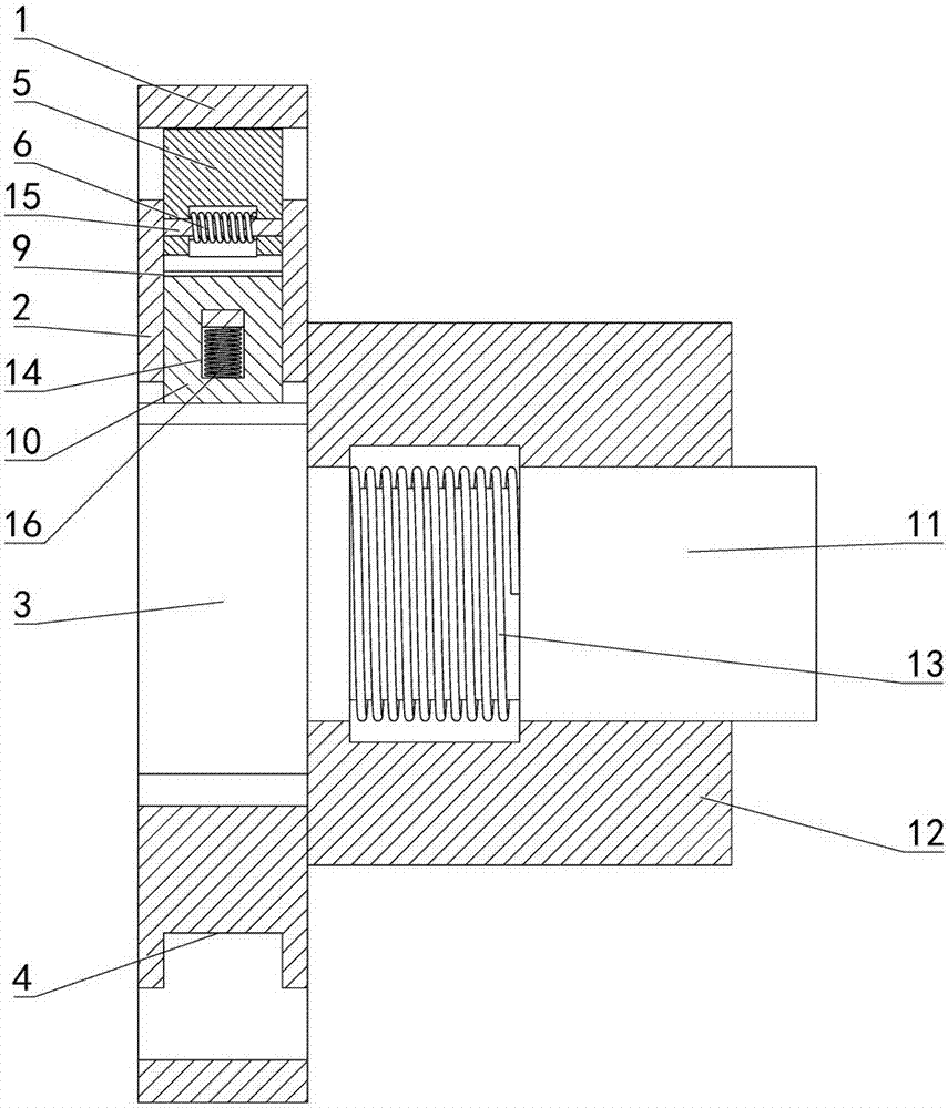
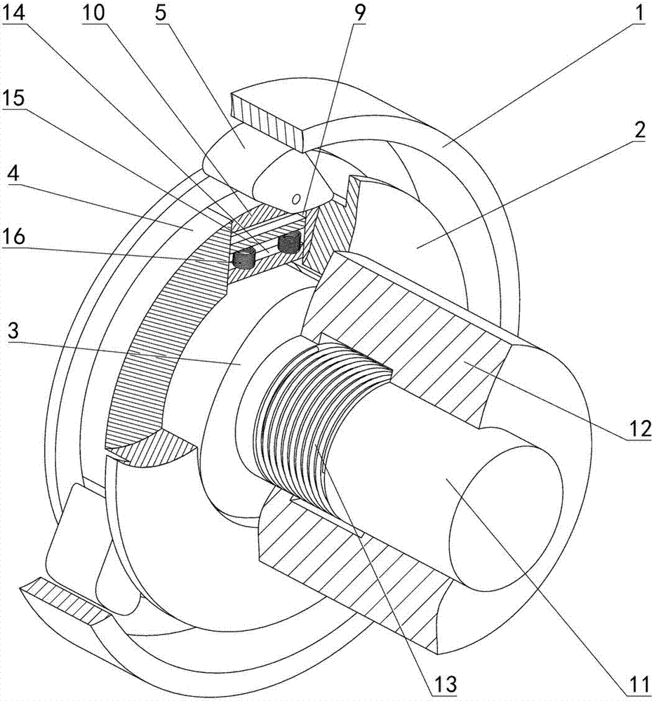
[0013] Depend on Figure 1 to Figure 3 Given, the present invention includes a fixed outer ring 1, an inner ring 2 placed inside the fixed outer ring 1 and a disc cam 3 placed inside the inner ring 2, and a circumferential groove 4 is provided on the outer edge surface of the inner ring 2, A plurality of wedges 5 evenly distributed on the circumference are hinged on the inner ring 2 through the end face of the circumferential groove 4. The hinged part of the wedges 5 is equipped with a torsion spring 6. One end of the torsion spring 6 is connected to the inner ring 2, and the other end is connected to the inner ring 2. The wedges 5 are connected to form a structure in which the wedges 5 are rotated on the inner ring 2 through the torsion spring 6 so that one end of the wedges 5 is pressed into contact with the fixed oute...


PUM


Abstract

The invention relates to a self-locking control device for hoisting equipment. According to the technical scheme, the self-locking control device comprises a fixed outer ring, an inner ring and a disc cam, the peripheral surface of the inner ring is provided with a circumferential groove, multiple wedge blocks are hinged to the end face of the circumferential groove, a torsional spring is installed on the hinged portion of each wedge block, one end of each torsional spring is connected with the inner ring, and the other end of each torsional spring is connected with the corresponding wedge block; the peripheral surface of the disc cam is formed by sequentially and smoothly connecting multiple convex parts and smooth parts which are evenly distributed, each convex part makes contact with the inner edge surface of the inner ring, the groove bottom of the circumferential groove is provided with multiple through grooves which are arranged in the radial direction of the inner ring, and the other end of each wedge block is arranged in the corresponding through groove; a sliding block is installed in each through groove, one end of each sliding block makes contact with the corresponding smooth part of the disc cam, and a gap exists between the other end of each sliding block and the other end of the corresponding wedge block; and an input shaft is installed on the disc cam, an output shaft is installed on the inner ring, and a torsional spring is installed between the input shaft and the output shaft. The self-locking control device for the hoisting equipment is ingenious in structure, convenient and rapid to operate and high in safety.

Description

technical field [0001] The invention relates to the field of lifting equipment, in particular to a self-locking control device for lifting equipment. Background technique [0002] During the working process of lifting equipment, in order to prevent the accidental fall of heavy objects due to its gravity, a reverse self-locking device is usually installed on the lifting equipment, especially hand hoists, chain hoists, hand cranks, etc. Some light-duty lifting equipment without power devices such as winches, and because such equipment mainly relies on manpower to complete the operation, it is particularly important to protect the safety of the operator. At present, most of this type of equipment is equipped with reverse self-locking devices, but these self-locking devices are mostly primitive control structures, such as self-locking springs or ratchet pawls. This structure is not only unreliable, but also inconvenient to operate, such as The commonly used ratchet and pawl str...

Claims


Application Information

Patent Timeline
Patent Type & Authority Applications(China)
IPC IPC(8): B66C15/00
CPCB66C15/00
Inventor 徐亚
Owner 河北战兴索具集团有限公司
Why Eureka
Try Eureka