Friction coupling for turnout switch machine

A switch machine and coupling technology, applied in the field of transportation, can solve the problems of large friction belt wear, high maintenance manpower, high production cost, etc., and achieve the effect of reducing friction, reducing investment and prolonging service life

Inactive Publication Date: 2020-11-10
万庆文
View PDF15 Cites 0 Cited by
  • Summary
  • Abstract
  • Description
  • Claims
  • Application Information

AI Technical Summary

Problems solved by technology

[0007] Aiming at the deficiencies in the use of the existing friction coupling proposed in the background technology, the present invention provides a friction coupling for a switch machine, which has the advantage of less wear of the friction belt, and solves the above-mentioned problems in the background technology. The problems of high maintenance manpower and high production cost caused by the large wear of the friction belt

Method used


Image

  • Friction coupling for turnout switch machine
  • Friction coupling for turnout switch machine
  • Friction coupling for turnout switch machine

Examples


Embodiment 1

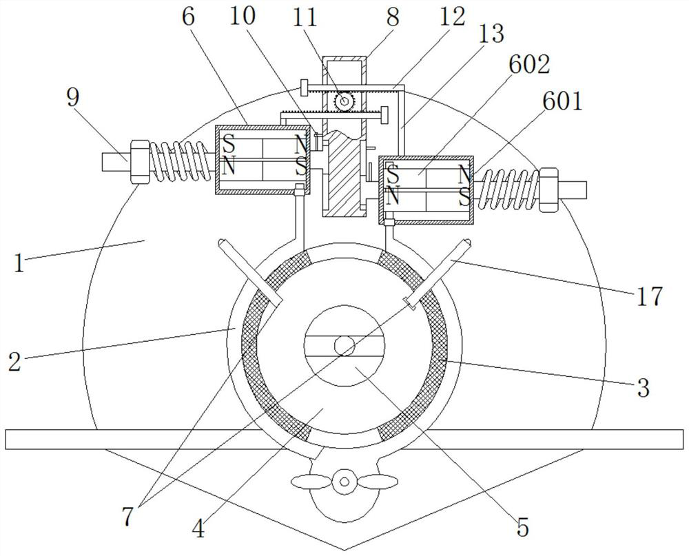
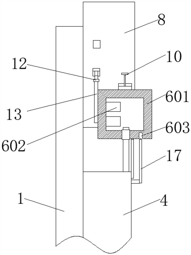
[0028] See attached Figure 1-2, the force applying structure 6 includes a housing 601 and a magnet group 602, the magnet group 602 is fixedly installed in the inner cavity of the housing 601, the magnet group 602 is two permanent magnet blocks with opposite polarities on the same side, and the two permanent magnet blocks are arranged up and down , the polarities of the opposite ends of the magnet groups 602 in the two force-applying structures 6 are respectively opposite, that is, when the heights of the two sets of magnet groups 602 are the same, the two symmetrical permanent magnet blocks of the same height attract each other, that is, the magnet groups 602 generally behave as attraction, when When the two groups of magnet groups 602 are located at the upper and lower limit positions respectively, the permanent magnet blocks at the high position of the magnet group 602 at the upper limit position and the permanent magnet blocks at the high position of the magnet group 602 at...

Embodiment 2

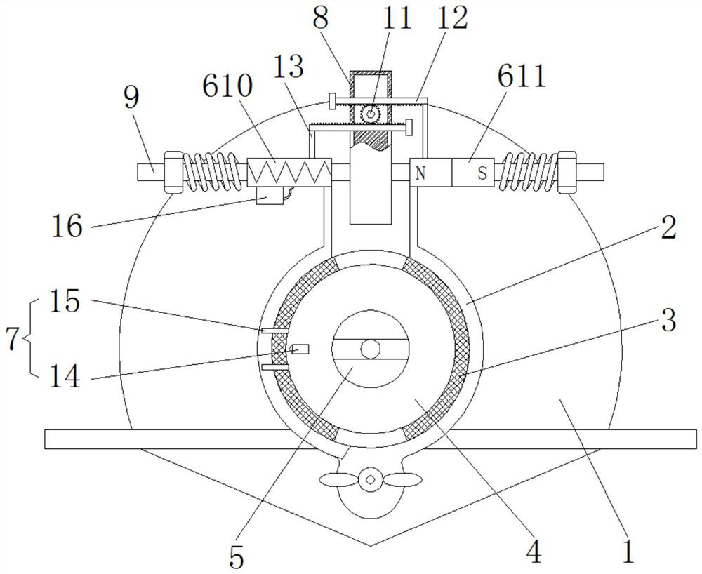
[0030] See attached image 3 As shown, the force applying structure 6 is set as an electromagnet 610 and a permanent magnet 611 respectively and is connected with the vertical bar of the friction brake plate 2. The rack 12 is connected, where the length of the support rod 13 can be fixed, the electromagnet 610 and the permanent magnet 611 are respectively slidably connected to the connecting rod 9, the connecting rod 9 is fixedly connected to the outer wall of the connecting box 8, and the permanent magnet 611 is electrically connected There is a current controller 16, and the current controller 16 feeds positive and negative currents into the electromagnet 610, so that the magnetic poles at the opposite ends of the electromagnet 610 and the permanent magnet 611 are opposite or the same, so as to achieve the purpose of attracting or repelling the permanent magnet 611 and the electromagnet 610; Trigger assembly 7 is set as magnetic head 14 and magnetic grid 15, when installing ...


PUM


Abstract

The invention relates to the technical field of traffic, and discloses a friction coupling for a turnout switch machine. The friction coupling comprises a speed reduction shell, an inner gear is arranged on the surface of the speed reduction shell, an output shaft is sleeved with the middle of the inner gear, and friction brake plates are arranged at the outer side of the inner gear. The number ofthe friction brake plates is two, and one ends of the friction brake plates are fixed to a clamping plate shaft of the speed reduction shell. Through the attraction or repulsion effect of a force application structure, the extrusion force of the friction brake plates acting on the inner gear is increased or decreased, so that the purpose of increasing or decreasing the friction force between a friction belt and the inner gear is achieved, the torque transmitted to the output shaft by a motor is increased in a normal state, and when a turnout is blocked, the abrasion of the friction belt caused by the inner gear is reduced, the adjustment frequency of the friction coupling is reduced, the labor investment is reduced, the service life of the friction belt is prolonged, and the production and maintenance cost is reduced.

Description

technical field [0001] The invention relates to the technical field of traffic, in particular to a friction coupling for a branch road switch machine. Background technique [0002] The electric switch machine friction coupling is a coupling device that protects the motor and absorbs the moment of inertia. Its functions: First, when the motor control circuit is cut off, the motor cannot stop rotating immediately, and the electric switch machine friction coupling makes the connection with it The output stops moving. The second is to prevent the motor from idling for a long time and burning out when the switch rail is blocked and cannot continue to switch. [0003] When the new electric switch machine operates, its motor is decelerated by gears, which drives the friction coupling to rotate. The friction coupler is connected with the ball screw through a flat key, thereby driving the ball screw to rotate, and the screw nut on the ball screw drives the push plate sleeve to perf...

Claims


Application Information

Patent Timeline
Patent Type & Authority Applications(China)
IPC IPC(8): F16D27/02F16D27/01F16D27/00F16D27/14B61L5/06H02K7/102
CPCF16D27/02F16D27/01F16D27/004F16D27/14B61L5/065H02K7/1023
Inventor 万庆文
Owner 万庆文
Why Eureka
Try Eureka