Whip restraint device and method for high-energy pipeline

A technology of high-energy pipelines and restricting devices, which is applied in the direction of pipe components, pipes/pipe joints/fittings, mechanical equipment, etc., can solve the problems of low resistance of high-energy pipelines, and achieve the effect of preventing slamming

Inactive Publication Date: 2017-09-15
HOHAI UNIV CHANGZHOU
View PDF6 Cites 4 Cited by
  • Summary
  • Abstract
  • Description
  • Claims
  • Application Information

AI Technical Summary

Problems solved by technology

The commonly used pipeline slam limiting device is a U-shaped (or other shape) metal structure. Considering the thermal displacement of the high-energy pipeline, a certain space must be left between the U-shaped slam limiting device and the high-energy pipeline during installation. It meets the thermal displacement requirements of the high-energy pipeline, but when the high-energy pipeline breaks at the elbow connection of the high-energy pipeline, the thermal displacement space of the high-energy pipeline reserved between the U-shaped slam limit device and the high-energy pipeline becomes a high-energy pipeline. The factors of pipeline acceleration and slamming energy increase. At the same time, when the U-shaped slamming limiting device is geometrically deformed, the U-shaped slinging limiting device has less resistance to the high-energy pipeline, and the slamming energy of the high-energy pipeline will continue to increase. When U When the U-shaped slam limiting device enters into plastic deformation, the U-shaped slam limiting device really begins to absorb and consume the slamming energy of the high-energy pipeline. At this time, the slamming energy of the high-energy pipeline is already very large. In addition, in the world, there is no test equipment that can truly simulate high-energy pipeline slamming and test the U-shaped slamming limiting device.

Method used


Image

  • Whip restraint device and method for high-energy pipeline

Examples


Embodiment Construction

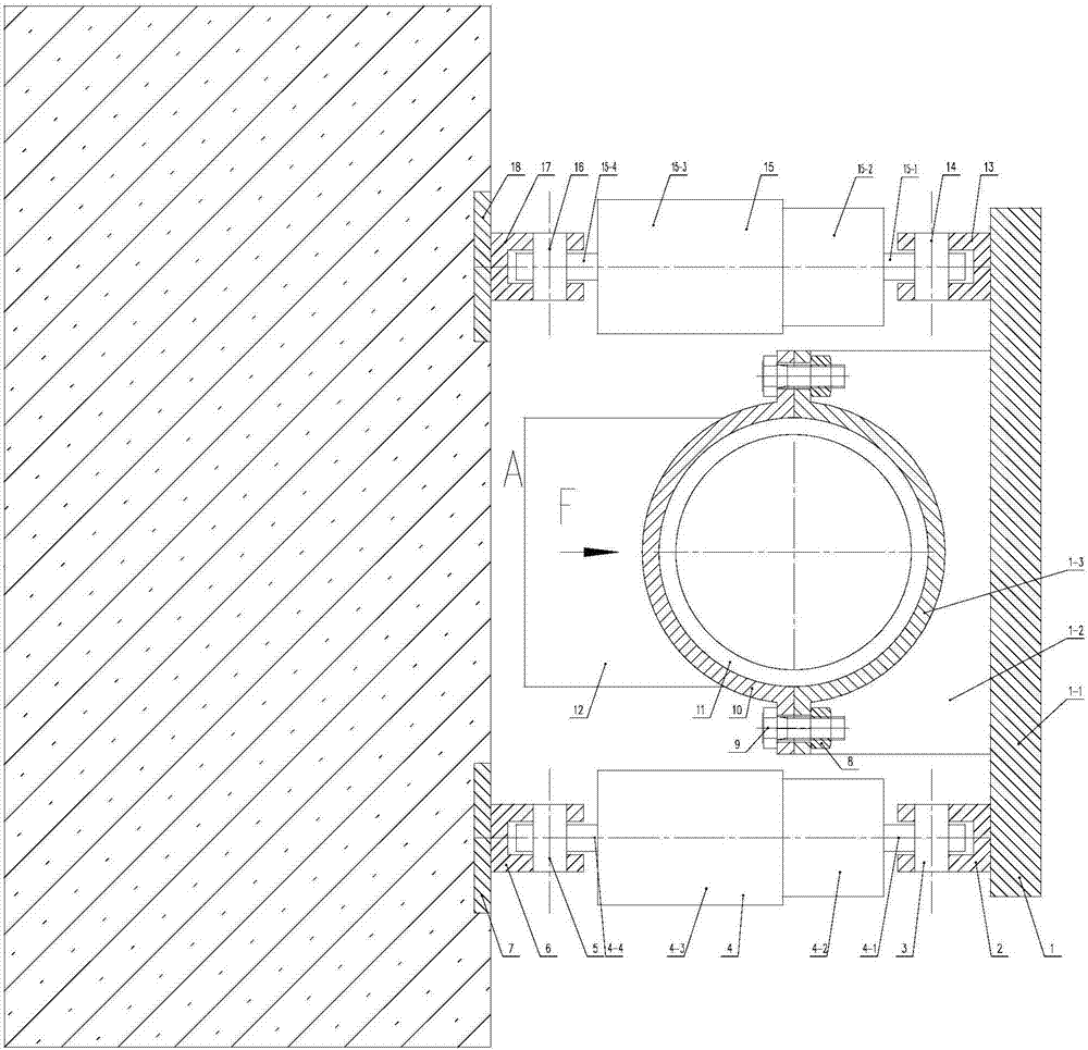
[0012] Such as figure 1 As shown, a high-energy pipeline slam limiting device includes a bracket assembly 1, a first pin seat 2, a first pin shaft 3, a first speed-sensitive hydraulic damper 4, a second pin shaft 5, and a second pin shaft Seat 6, nut 8, bolt 9, plate type arc pipe collar 10, third pin seat 13, third pin shaft 14, second speed-sensitive hydraulic damper 15, fourth pin shaft 16, fourth pin seat 17; Described bracket assembly 1 comprises bracket bottom plate 1-1, bracket vertical plate 1-2, arc-shaped supporting plate 1-3, and the right end of bracket vertical plate 1-2 is welded with bracket bottom plate 1-1, and bracket The left end of the frame vertical plate 1-2 is welded with the arc-shaped supporting plate 1-3, and the bracket bottom plate 1-1, the bracket vertical plate 1-2, and the arc-shaped supporting plate 1-3 are welded to each other to form a bracket assembly 1; The first speed-sensitive hydraulic damper 4 includes the first damper movable part pin ...


PUM


Abstract

The invention discloses a whip restraint device and method for a high-energy pipeline. The whip restraint device comprises a bracket assembly, a first pin base, a first pin shaft, a first speed sensitive hydraulic damper, a second pin shaft, a second pin base, nuts, bolts, a plate type arc pipe clamp, a third pin base, a third pin shaft, a second speed sensitive hydraulic damper, a fourth pin shaft and a fourth pin base. Each of the parts, near the two sides of a high-energy pipeline elbow, of the high-energy pipeline is provided with one or more whip restraint device bodies. When the high-energy pipeline generates heat displacement, the speed sensitive hydraulic dampers follow the high-energy pipeline, and only small resisting force is generated to the high-energy pipeline; and when the high-temperature pipeline is broken at the high-energy pipeline elbow, the speed sensitive hydraulic dampers are locked, and due to rated resisting force formed for the high-energy pipeline, other key devices and the high-energy pipeline are effectively protected.

Description

technical field [0001] The invention relates to a pipeline sling limiting device and method, in particular to a high-energy pipeline sling limiting device and method, belonging to the fields of electrical and electromechanical technology and energy security. Background technique [0002] At present, high-energy pipelines are widely used in the fields of nuclear power and chemical industry. For high-energy pipelines, if a pipe break occurs at the elbow joint of the high-energy pipeline, high-pressure steam will be ejected, which will generate a continuous large force on the high-energy pipeline. The high-energy pipeline forms a slam. Due to the continuous injection of high-pressure steam, the slam kinetic energy of the high-energy pipeline will continue to increase. If the high-energy pipeline touches other key equipment during the slam process, it will impact other key equipment with huge energy, causing serious damage. Secondary accidents, in order to prevent high-energy pi...

Claims


Application Information

Patent Timeline
Patent Type & Authority Applications(China)
IPC IPC(8): F16L55/00
CPCF16L55/005
Inventor 钱雪松
Owner HOHAI UNIV CHANGZHOU
Why Eureka
Try Eureka