
Power device loss test method

A technology of power devices and testing methods, which is applied in the direction of instruments, measuring devices, measuring electrical variables, etc., can solve the problems of test result error, unstable initial temperature change, and failure to consider the influence of ambient temperature, etc., and achieve short test time, The effect of avoiding the influence of the initial temperature instability

Active Publication Date: 2017-09-15
HEFEI UNIV OF TECH
View PDF6 Cites 4 Cited by
  • Summary
  • Abstract
  • Description
  • Claims
  • Application Information

AI Technical Summary

Problems solved by technology

However, this test method does not take into account the influence of the ambient temperature on the test results. At the same time, when the power device starts to work, the initial temperature change is not stable, resulting in errors in the test results.

Method used


Image

  • Power device loss test method

Examples


Embodiment Construction

[0034] In order to make the object, technical solution and advantages of the present invention more clear, the present invention will be further clearly and completely described below in conjunction with the accompanying drawings and embodiments.

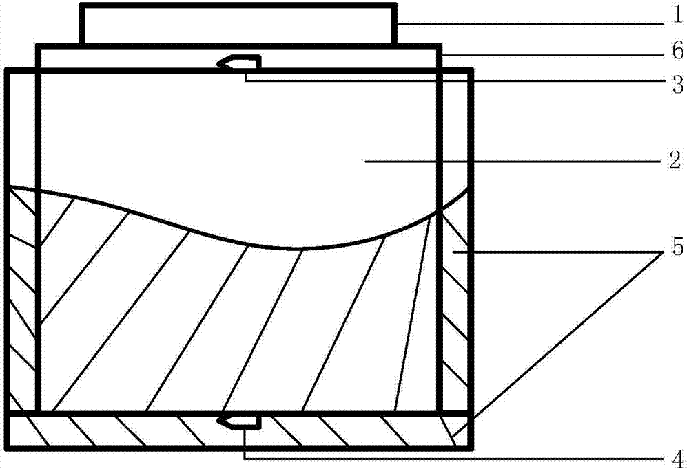
[0035] figure 1It is a device structure diagram of an embodiment of the present invention. It can be seen from this figure that the test device involved in this test method includes a power device to be tested 1, a cubic metal block 2, a first temperature probe 3, a second temperature probe 4, and a heat insulating material 5 and a heat-conducting rubber pad 6; the heat-conducting rubber pad 6 is bonded on the upper end face of the cube metal block 2, and the five faces of the cube metal block 2 except the upper end face are wrapped with heat-insulating materials 5; The first temperature probe 3 is installed between the upper end surface of the cubic metal block 2 and the heat-conducting rubber pad 6, and the second temperature prob...


PUM


Abstract

The invention discloses a power device loss test method. The method includes the following steps: (1) a loss correction test which is intended for drawing a loss curve describing how the loss of a to-be-tested power device changes over temperature differences; (2) an actual circuit test which is intended for enabling the to-be-tested power device to work normally and obtaining the power value of the to-be-tested power device on the basis of the curve which is obtained in the loss correction test in correspondence to the temperature difference from actual measurement. The method can obtain loss values under actual working conditions, can meet test requirements under any working condition, overcomes measurement errors caused by inaccuracy and delay of electric measuring devices (such as an oscilloscope), can produce a test result which is free from instability of environment temperature and starting temperature, and can obtain accurate power device loss data.

Description

technical field [0001] The invention relates to a power device loss testing method, which belongs to the technical field of power electronics. Background technique [0002] With the continuous development of power electronic technology, power electronic devices tend to be more and more high-frequency, high-power and highly integrated. The study of device loss can provide guidance for device selection and heat dissipation design in power conversion device systems, and at the same time provide an important basis for optimizing system efficiency. [0003] In recent years, the research on the loss of power electronic devices has always been a very important research direction in the field of power electronics. The most widely used research method is to estimate the device loss based on the data given in the device data sheet. This method relies on the manuals provided by power electronic device manufacturers, determines parameters such as voltage, current, and duty cycle throug...

Claims


Application Information

Patent Timeline
Patent Type & Authority Applications(China)
IPC IPC(8): G01R27/26
CPCG01R27/2694
Inventor 张兴冯之健王佳宁许明明韦武
Owner HEFEI UNIV OF TECH
Learn More