
A bias current and power-on reset circuit for a shutdown chip

A technology of bias current and power-on reset, which is applied in the field of analog integrated circuits and circuits, can solve the problems of entering the normal working mode, the bias circuit and power-on reset circuit cannot work normally, and the chip cannot be powered on, so as to avoid downtime Logical confusion, improving reliability, and ensuring the effect of logical correctness

Active Publication Date: 2020-03-27
上海趣致网络科技有限公司
View PDF6 Cites 0 Cited by
  • Summary
  • Abstract
  • Description
  • Claims
  • Application Information

AI Technical Summary

Problems solved by technology

Since the shutdown signal controls the shutdown of the bias circuit and the power-on reset circuit at the same time, it may cause the shutdown signal to be in an effective shutdown state (usually logic 1) before the power-on reset circuit generates a reset signal, thereby biasing the circuit and The power-on reset circuit cannot work normally, and the entire chip cannot be powered on and enters the normal working mode

Method used


Image

  • A bias current and power-on reset circuit for a shutdown chip
  • A bias current and power-on reset circuit for a shutdown chip
  • A bias current and power-on reset circuit for a shutdown chip

Examples


Embodiment Construction

[0058] The present invention will be further described below in conjunction with the embodiments shown in the accompanying drawings.

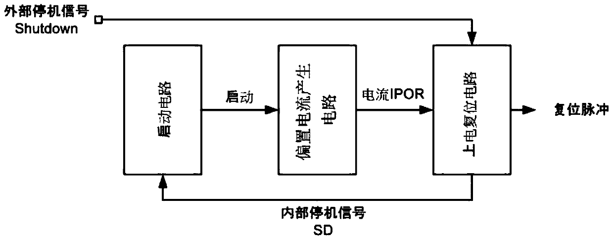
[0059] The present invention proposes a bias current and power-on reset circuit for a shutdown chip, figure 1 Shown is its structural block diagram.

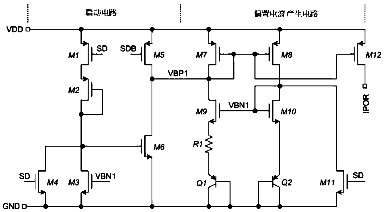
[0060] The bias current and power-on reset circuit of the shutdown chip includes a power-on reset circuit and a current bias circuit connected to each other, and the current bias circuit includes a start-up circuit and a bias current generation circuit connected to each other. Wherein: when the power-on reset circuit is powered on, the logic of the shutdown signal is guaranteed to be non-shutdown logic (0 in this embodiment), until the startup circuit charges the bias current generation circuit in the process until the shutdown chip gets rid of degeneracy bias point. The power-on reset circuit is also used to generate a power-on reset signal after power-on, and monitor the external shutdown sig...


PUM


Abstract

The invention provides bias current and a power-on reset circuit for shutdown chips and belongs to the technical field of analogue integrated circuits. The bias current and the power-on reset circuit for shutdown chips comprise interconnected power-on reset circuit and current biasing circuit; wherein the current biasing circuit comprises interconnected start-up circuit and bias current generation circuit. When a power-on reset circuit is being powered on, ensuring that the logic of the shutdown signal is non-stop logic until, during this process, the bias current generation circuit is charged by the start-up circuit until the shutdown chip is free of degeneracy bias points. The power-on reset circuit is also used for generating power-on reset signals after the completion of power-on, monitoring external shutdown signals and making the bias current generate a circuit into a high impedance state when the logic of the external shutdown signal is the shutdown logic, then the shutdown chip enters shutdown state. The invention can ensure the normal start-up and shutdown of chips, greatly increasing the reliability of shutdown and start-up of chips.

Description

technical field [0001] The invention belongs to the technical field of analog integrated circuits, and relates to a circuit, especially a bias current and power-on reset circuit. Background technique [0002] Bias circuit and power-on reset circuit are indispensable components in modern chips, which respectively provide voltage / current bias and reset logic for other circuits in the chip to avoid unstable logic states. [0003] Today, low-power design is an important norm in the field of integrated circuit design. For common long-time continuous working circuits such as bias circuits and power-on reset circuits, the demand for low power consumption requires them to have shutdown and restart functions. Usually, the shutdown of the circuit is controlled by the shutdown signal, but during the power-on process, before the power-on reset circuit sends the power-on reset signal, the logic in the chip (including the shutdown signal) is in a logic unstable state. Since the shutdown...

Claims


Application Information

Patent Timeline
Patent Type & Authority Patents(China)
IPC IPC(8): G06F1/24G06F1/26
CPCG06F1/24G06F1/26
Inventor 黄爱华王健余生
Owner 上海趣致网络科技有限公司
Learn More