Display panel and display device

A technology of display panel and display area, which is applied in identification devices, nonlinear optics, optics, etc., can solve the problems of display panel being difficult to achieve narrow frame design, large area, and fan-out area occupation.

Active Publication Date: 2017-09-15
XIAMEN TIANMA MICRO ELECTRONICS
View PDF13 Cites 28 Cited by
  • Summary
  • Abstract
  • Description
  • Claims
  • Application Information

AI Technical Summary

Problems solved by technology

Moreover, the fan-out leads in the display panel are usually arranged on the same metal layer, which makes the fan-out area need to occupy a larger area in the lower frame area
However, in the display panel packaged by COF technology, the area of ​​the lower frame area between the display area and the flexible circuit board is relatively small. Therefore, in order to meet the area requirements of the fan-out area, it is necessary to increase the area between the display area and the flexible circuit board. The distance between them will make it difficult to realize the narrow bezel design of the display panel

Method used


Image

  • Display panel and display device
  • Display panel and display device
  • Display panel and display device

Examples


Embodiment Construction

[0013] The principles and features of the present application will be further described in detail below in conjunction with the drawings and embodiments. It should be understood that the specific embodiments described here are only used to explain related inventions, rather than to limit the invention. It should also be noted that, for ease of description, only parts related to the invention are shown in the drawings.

[0014] It should be noted that, in the case of no conflict, the embodiments in the present application and the features in the embodiments can be combined with each other. The present application will be described in detail below with reference to the accompanying drawings and embodiments.

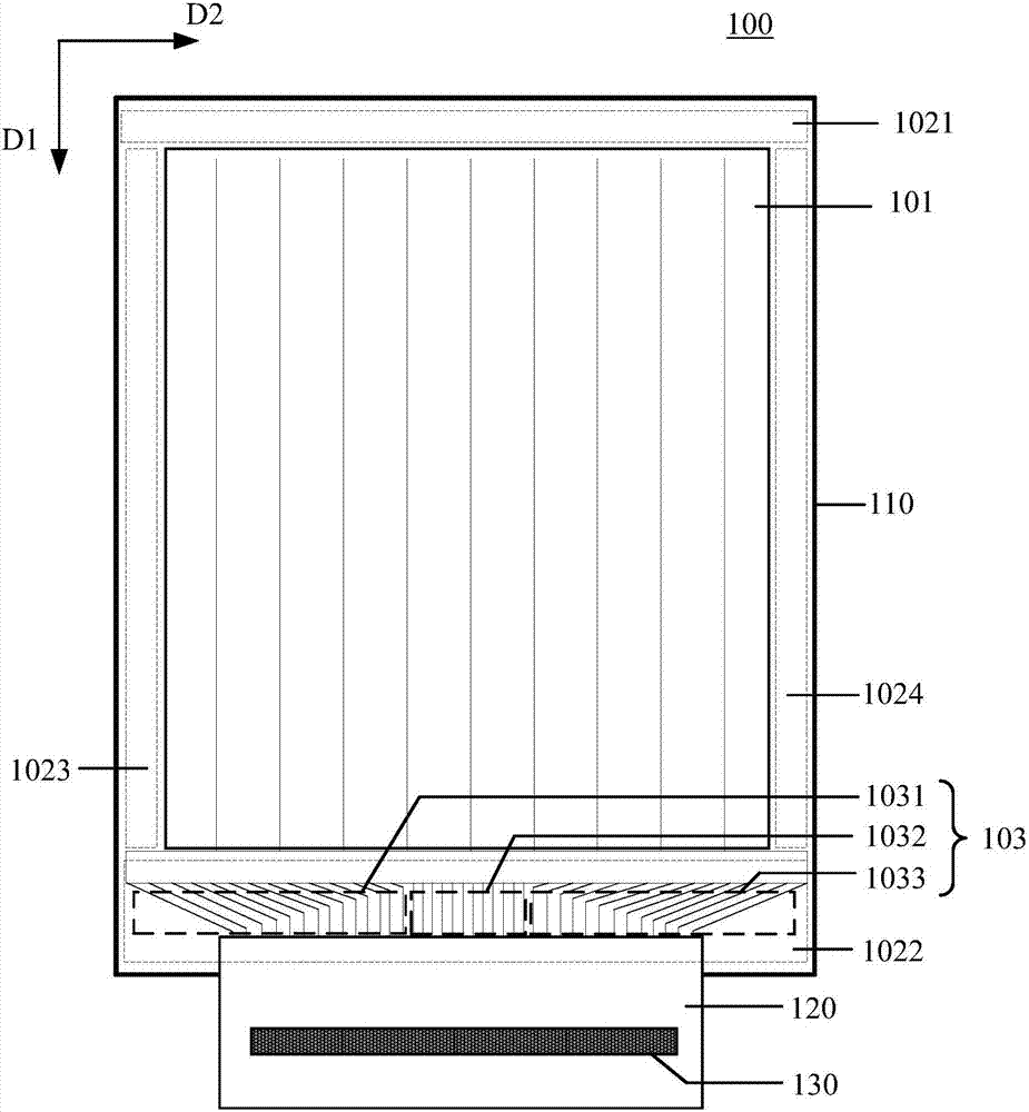
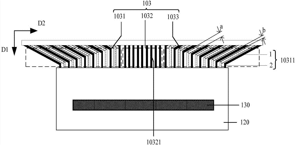
[0015] Please refer to Figure 1A-1B ,in, Figure 1A shows a schematic structural diagram of an embodiment of a display panel according to the present application, Figure 1B show Figure 1A A schematic diagram of the connection relationship between the first fan-out lea...


PUM


Abstract

The invention discloses a display panel and a display device. The display panel comprises a display area and a non-display area, wherein the non-display area comprises an upper border area and a lower border area which are arranged in the first direction; a fan-out area is located in the lower border area and comprises a first sub fan-out area, a second sub fan-out area and a third sub fan-out area which are sequentially arranged in the second direction, the first sub fan-out area and the third sub fan-out area comprise multiple first fan-out leads, the second sub fan-out area comprises multiple second fan-out leads, the first fan-out leads which are located in the first sub fan-out area and the third sub fan-out area and sequentially arranged in the second direction are alternately arranged on a first metal layer and a second metal layer, and the second fan-out leads are arranged on the second metal layer. The first fan-out leads in the first sub fan-out area and the third sub fan-out area are alternately arranged on the first metal layer and the second metal layer, so that the height of the lower border area in the first direction can be reduced, and narrow border design of the display panel can be realized.

Description

technical field [0001] The present application relates to the field of display technology, and in particular to a display panel and a display device including the display panel. Background technique [0002] The driving chip packaging technology of the display panel mainly includes COG (Chip on glass) technology and COF (Chip on flim) technology. At present, the packaging of the driver chip in the display panel mainly adopts the COF technology, and the driver chip is directly packaged on the flexible circuit board. Since the COF technology can package the driver chip on the flexible circuit board instead of the lower frame area of ​​the non-display area of ​​the display panel, the area of ​​the lower frame area of ​​the non-display area of ​​the display panel packaged by COF technology is smaller, thereby increasing The area occupied by the display area of ​​the display panel. [0003] In a display panel packaged with COF technology, data lines and the like can be electric...

Claims


Application Information

Patent Timeline
Patent Type & Authority Applications(China)
IPC IPC(8): G09F9/00G02F1/1345
CPCG02F1/13452G09F9/00
Inventor 蔡寿金朱绎桦贝亮亮陈国照
Owner XIAMEN TIANMA MICRO ELECTRONICS
Why Eureka
Try Eureka