stator of electric machine

A stator and machine technology, applied in the field of placing various windings in the center, can solve the problems of accessibility and difficulty in embedding

Active Publication Date: 2020-02-04
VOLKSWAGEN AG
View PDF4 Cites 0 Cited by
  • Summary
  • Abstract
  • Description
  • Claims
  • Application Information

AI Technical Summary

Problems solved by technology

However, due to the accessibility of the notch area of ​​the winding slot towards the inner side of the ring, the sliding cage is more difficult to insert here, especially if the sliding cage is designed to be dimensionally stable and the winding protrudes laterally out of the stator body.

Method used


Image

  • stator of electric machine
  • stator of electric machine
  • stator of electric machine

Examples


Embodiment Construction

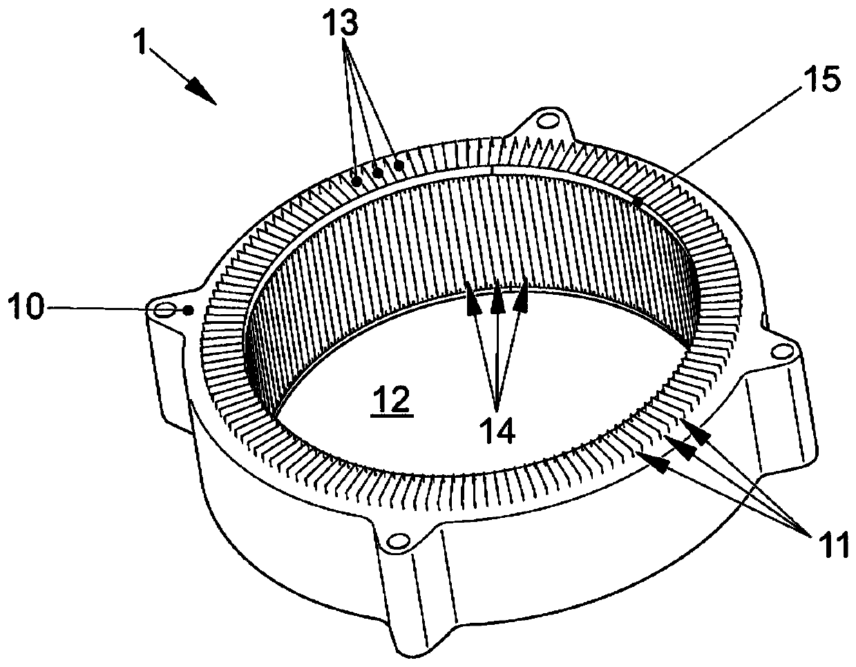
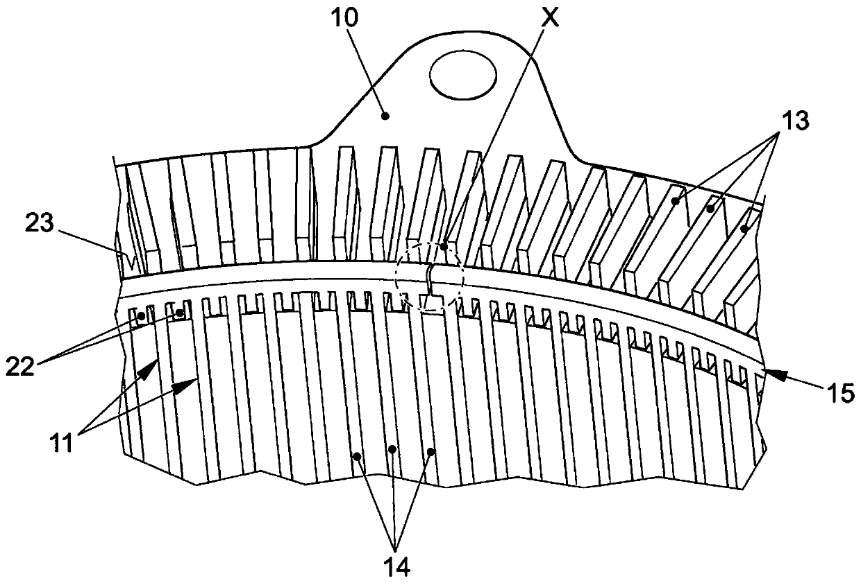
[0025] figure 1 A stator 1 for an electric machine is shown in perspective and has an annular stator body 10 as a main component, wherein the ring describes the basic structure of the stator body 10 . A ring inner side 12 is formed within the annular stator body 10 , and from the ring inner side 12 an annular groove 11 extends radially outward into the stator body 10 and into which a winding 13 engages. To form an electric machine, a rotor is arranged in the inner ring 12 and performs a rotation in the inner ring 12 when the winding 13 is energized in a correspondingly controlled manner. Ring inner side 12 substantially forms a cylindrical jacket shape and has an axial direction which describes the width direction of stator body 10 , and winding slots 11 protrude radially into stator body 10 from the inside to the outside.

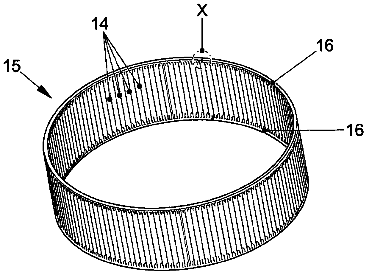
[0026] The insertion of a sliding cover cage 15 into the stator body 10 is shown from the ring inner side 12 , and the sliding cover cage 15 has a plural...


PUM


Abstract

The invention relates to a stator (1) of an electric machine, which has an annular stator body (10), in which a plurality of winding slots (11) are arranged, wherein the winding slots (11) are arranged from the inner side (12) of the ring protrudes into the stator body (10) in the form of pockets, and wherein the individual windings (13) are inserted into winding slots (11), which are each closed by means of sliding cover elements (14) towards the ring inner side (12), And wherein the slide elements (14) of all winding slots (11) are connected into a slide cage (15), wherein the slide cage (15) has a surrounding cage ring (16) on the end of the slide element (14) ). According to the invention, said cage ring (16) is broken at a circumferential position (X), wherein said circumferential position (X) has a self-locking locking structure (17) which prevents the cage ring ( Automatic opening of the two intermeshing ring ends (18,19) of 16).

Description

technical field [0001] The invention relates to a stator of an electric machine, which has an annular stator body, and a plurality of winding slots are processed in the stator body, wherein the winding slots protrude into the stator body from the inner side of the ring in a pocket shape, and wherein the winding slots The individual windings are arranged, which are each closed by means of a sliding cover element towards the inside of the ring, and wherein the sliding cover elements of all winding slots are combined to form a sliding cover cage, wherein the sliding cover cage has a surrounding cage ring at the end of the sliding cover element. Background technique [0002] Patent DE102004015243B4 discloses a stator of an electric machine, which has an annular stator body, and a plurality of winding slots are processed in the stator body, and the windings are embedded in the winding slots, and the windings are loaded into the pocket-shaped windings from the inside of the ring i...

Claims


Application Information

Patent Timeline
Patent Type & Authority Patents(China)
IPC IPC(8): H02K3/487
CPCH02K3/487H02K1/165H02K1/185
Inventor M.菲普尔U.雷门施奈德M.施尼尔
Owner VOLKSWAGEN AG
Why Eureka
Try Eureka