Optical fiber winding device for optical fiber macrobending loss measurement and optical fiber winding method

A technology of optical fiber macrobending and winding device, applied in the direction of testing optical performance, etc., can solve the problem of inability to effectively eliminate the torsional stress of optical fiber, and achieve the effect of clear design principle, guaranteed accuracy and convenient operation

Active Publication Date: 2017-09-19
CHINA ACADEMY OF INFORMATION & COMM
View PDF6 Cites 6 Cited by
  • Summary
  • Abstract
  • Description
  • Claims
  • Application Information

AI Technical Summary

Problems solved by technology

The first solution of the existing macrobending loss device is to use both ends of the optical fiber as free ends, and rotate the optical fiber disk and the mandrel at the same time to achieve the purpose of eliminating torsional stress, but this cannot be achieved without secondary treatment of the optical fiber end face. Complete the macro bending loss test under
The second solution is to fix the optical fiber reel, take off the optical fiber from the reel one by one and wind it on the mandrel. This method cannot effectively eliminate the torsional stress of the optical fiber caused by the change of the winding radius, which affects the test results.
There is no macrobending loss device reported so far, which can not only realize the loose winding treatment of the optical fiber while eliminating the torsional stress, but also realize the completion of the test without secondary end surface treatment.

Method used


Image

  • Optical fiber winding device for optical fiber macrobending loss measurement and optical fiber winding method
  • Optical fiber winding device for optical fiber macrobending loss measurement and optical fiber winding method
  • Optical fiber winding device for optical fiber macrobending loss measurement and optical fiber winding method

Examples


Embodiment Construction

[0042]In order to make the purpose, technical solutions and advantages of the embodiments of the present invention clearer, the technical solutions in the embodiments of the present invention will be clearly and completely described below in conjunction with the drawings in the embodiments of the present invention. Obviously, the described embodiments It is a part of embodiments of the present invention, but not all embodiments. Based on the embodiments of the present invention, all other embodiments obtained by persons of ordinary skill in the art without creative efforts fall within the protection scope of the present invention.

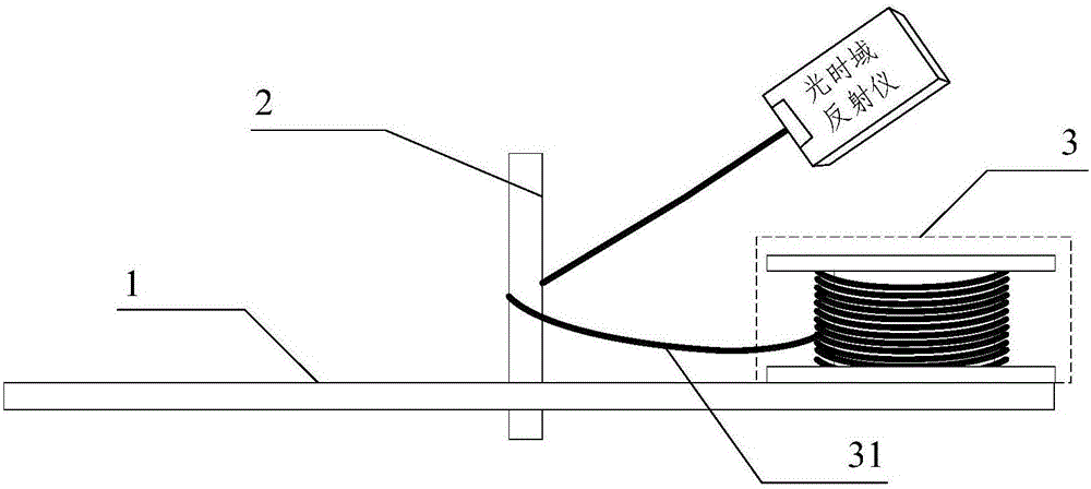
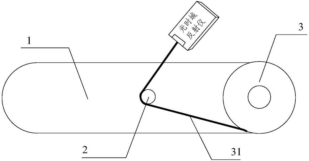
[0043] Embodiment 1 of the present invention provides a specific implementation of an optical fiber winding device for measuring optical fiber macrobending loss. see figure 1 and 2 , the optical fiber winding device specifically includes the following contents:

[0044] A rotating bracket 1 arranged horizontally, a mandrel 2 vertically arranged ...


PUM


Abstract

The invention provides an optical fiber winding device for optical fiber macrobending loss measurement and an optical fiber winding method. The optical fiber winding device comprises a horizontally arranged rotating bracket and a core shaft vertically arranged at the center of the rotating bracket, and is characterized in that an end plate at one end of the rotating bracket is used for placing an optical fiber reel, the core shaft and the rotating bracket are movably connected, and the bottom end of the core shaft penetrates through the rotating bracket and is fixedly arranged; the optical fiber reel is arranged on the end plate at one end of the rotating bracket, one end of an optical fiber on the optical fiber reel is fixed on the core shaft, the rotating bracket rotates by taking the core shaft as an axis, and the optical fiber reel rotates towards a direction opposite to the rotating direction of the rotating bracket while moving along with the rotating bracket. The optical fiber winding device can achieve a purpose of directly winding an optical fiber without removing the optical fiber on an optical time-domain reflectometer, avoids an attenuation error generated in optical fiber macrobending loss measurement, ensures the optical fiber not to generate torsion stress in the winding process through the overall device structure and ensures the accuracy of optical fiber macrobending loss measurement.

Description

technical field [0001] The invention relates to the field of optical fiber loss measurement, in particular to an optical fiber winding device and method for optical fiber macrobending loss measurement. Background technique [0002] Optical fiber is the core component of optical cable. Since the optical communication network is composed of optical cables, the performance of optical fibers has a crucial impact on the speed, bandwidth, and quality of communication. During the construction and use of optical cables, especially in the part of the access network, since the laying of optical cables will produce more bends, the bending performance of optical fibers has become an important indicator to measure the quality of optical cables. A key indicator of flex performance. [0003] Bending the optical fiber is an important step in the macrobend loss test. IEC 60793-1-47:2009 "Optical fibers-Part 1-47: Measurement methods and test procedures-Macrobending loss" stipulates two me...

Claims


Application Information

Patent Timeline
Patent Type & Authority Applications(China)
IPC IPC(8): G01M11/02
CPCG01M11/02
Inventor 韩超刘泰吕捷李婷婷翟庆诗王尧
Owner CHINA ACADEMY OF INFORMATION & COMM
Why Eureka
Try Eureka