
Method for computing ice melting time of power transmission lines in consideration of water films

A transmission line and time calculation technology, which is applied to measuring devices, instruments, scientific instruments, etc., can solve the problems of different heat conduction, poor practicability and calculation accuracy of the calculation model for melting ice of transmission wires, and no consideration of water film, etc., to achieve Accurate heat analysis, prevention of power grid ice disaster accidents, and improvement of the effect of ice melting technology

Active Publication Date: 2017-09-19
ELECTRIC POWER SCI RES INST OF GUIZHOU POWER GRID CO LTD
View PDF3 Cites 4 Cited by
  • Summary
  • Abstract
  • Description
  • Claims
  • Application Information

AI Technical Summary

Problems solved by technology

[0004] The technical problem to be solved by the present invention is to provide a method for calculating the ice melting time of transmission lines considering the water film; to solve the problem that the ice melting model of the transmission line in the prior art adopts a cylinder model and does not take into account the water film generated during the ice melting process At the same time, when the ice layer melts, a water film of a certain thickness will be produced, and the heat conduction of the water film and ice is different; these factors are not considered in the existing technology, which leads to the practicability and calculation accuracy of the calculation model for the ice melting of the transmission wire. Poor technical issues

Method used


Image

  • Method for computing ice melting time of power transmission lines in consideration of water films
  • Method for computing ice melting time of power transmission lines in consideration of water films
  • Method for computing ice melting time of power transmission lines in consideration of water films

Examples


Embodiment Construction

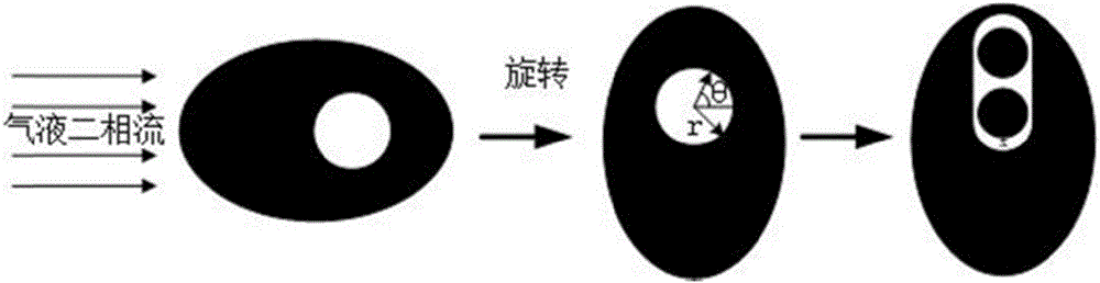
[0036] The invention provides a method for calculating the ice-melting time of a power transmission line considering the water film. Before the melting of ice begins, the wire and the ice layer are considered to be at the same temperature as the environment, and the wire is a good conductor of heat. During the melting process, the wire is regarded as an isothermal body. like figure 1 The icing formation and melting process are shown in four stages: the first stage, elliptical icing, under the influence of the wind, the ice on the windward side of the wire is more iced than the leeward side; the second stage, Melting ice produces a water film. After the ice melting begins, the inner surface of the ice layer that is in direct contact with the wire will be melted first after the temperature of the conductor rises to 0I, and a water film with a thickness of x will be produced; in the third stage, the ice layer rotates, under the action of gravity The icicle moves in the vertical ...


PUM


Abstract

The invention discloses a method for computing the ice melting time of power transmission lines in the consideration of water films. The method includes steps of 1, setting the conductor temperatures T<w>, ice layer temperatures T and environmental temperatures T<e> as T<s> before ice starts to be melted; 2, computing the areas A<m> of molten ice regions and the areas A<r> of remaining regions; 3, computing heat Q<1> required to be absorbed when the temperatures T<w> of conductors are increased and reach 0 DEG C; 4, computing heat Q<2> required to be absorbed when the temperatures T of the ice are increased and reach 0 DEG C; 5, computing heat required to continue being absorbed by the ice and melting the ice to obtain water; 6, computing heat Q<4> required to be absorbed by remaining ice layers; 7, computing heat Q<5> dissipated from the surfaces of the ice layers; 8, computing the ice melting time t. The method has the advantages that the heat can be accurately analyzed in ice melting procedures, and accordingly parameters such as the heat required for melting the ice by means of electric heating and the ice melting time can be accurately computed; theoretical bases can be provided for designing electric heating ice melting devices and selecting ice melting schemes for the power transmission lines.

Description

technical field [0001] The invention belongs to the ice-melting technology of transmission lines, and in particular relates to a method for calculating the ice-melting time of transmission lines considering water film. Background technique [0002] The electrothermal deicing calculation model of transmission lines is the theoretical basis for designing deicing devices and selecting deicing schemes. A reasonable deicing model is conducive to studying the influence of various influencing factors on the deicing process. The ice-melting time provides a theoretical basis, which is of great significance for improving the power grid's ability to prevent ice disasters and improving ice-melting technology. [0003] In the prior art, most studies on transmission line icing focus on the formation process and influencing conditions of icing, and there are few studies on transmission line icing process and electrothermal icing characteristics. In the existing ice-melting models, the cyl...

Claims


Application Information

Patent Timeline
Patent Type & Authority Applications(China)
IPC IPC(8): G01N25/00
Inventor 马晓红代洲毛先胤曾华荣许逵张迅田承越牛唯周羽生熊强边瑞恩甘凌霄
Owner ELECTRIC POWER SCI RES INST OF GUIZHOU POWER GRID CO LTD
Features
  • Generate Ideas
  • Intellectual Property
  • Life Sciences
  • Materials
  • Tech Scout
  • Unparalleled Data Quality
  • Higher Quality Content
  • 60% Fewer Hallucinations
Learn More