
Radar Transmitting Beam Nulling Method Based on AM and Phase Modulation Auxiliary Antenna

An auxiliary antenna and transmitting beam technology, which is applied in anti-interference and anti-interception, anti-reconnaissance of radar transmitted signals, and signal processing fields, can solve problems such as large amount of calculation, and achieve the effect of avoiding large amount of calculation

Active Publication Date: 2020-02-21
XIDIAN UNIV
View PDF2 Cites 0 Cited by
  • Summary
  • Abstract
  • Description
  • Claims
  • Application Information

AI Technical Summary

Problems solved by technology

[0005] The purpose of the present invention is to address the deficiencies in the prior art above, and propose a radar transmit beam nulling method based on the AM / PM auxiliary antenna, which is used to solve the calculation amount existing in the existing amplitude-phase weighted transmit beam zeroing method big technical problem

Method used


Image

  • Radar Transmitting Beam Nulling Method Based on AM and Phase Modulation Auxiliary Antenna
  • Radar Transmitting Beam Nulling Method Based on AM and Phase Modulation Auxiliary Antenna
  • Radar Transmitting Beam Nulling Method Based on AM and Phase Modulation Auxiliary Antenna

Examples


Embodiment Construction

[0022] The present invention will be described in further detail below in conjunction with the accompanying drawings and specific embodiments.

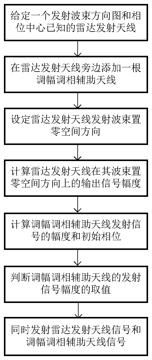
[0023] refer to figure 1 , a radar transmit beam zeroing method based on an AM / PM auxiliary antenna, comprising the following steps:

[0024] Step 1. Given a radar transmitting antenna with a known phase center, the transmitting beam pattern of the transmitting antenna is p o (f a ), where f a Represents the azimuth angle of the antenna, the radar transmitting antenna can be a radar transmitting antenna, or an antenna array composed of several antennas of the same specification and performance, in this embodiment, a uniform linear array with 5 array elements is used as the radar transmitting antenna;

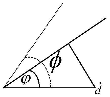
[0025] Step 2, add a transmit beam pattern next to the radar transmit antenna as p A (f a ), the maximum transmit signal amplitude is α max AM and phase modulation auxiliary antenna, the distance vector between the phase center of...


PUM


Abstract

The invention provides a radar emission wave beam zero setting method based on an amplitude modulation and phase modulation auxiliary antenna. The objective of the invention is to solve a technical problem of big calculated quantity in the emission wave beam zero setting method based on amplification and phase weighting. The method comprises steps of giving a radar emission antenna; adding an amplitude modulation and phase modulation auxiliary antenna next to the radar emission antenna; setting the space direction of wave beam zero setting of the radar emission antenna; calculating output signal amplitude of the radar emission antenna in the wave beam zero setting space direction; calculating the amplitude and the initial phase position of the emission signal of the amplitude modulation and phase modulation auxiliary antenna; judging the value of the emission signal amplitude of the amplitude modulation and phase modulation auxiliary antenna; and emitting a radar emission antenna signal and an amplitude modulation and phase modulation auxiliary antenna signal so as to obtain a synthesis direction graph of the radar emission antenna in the wave beam zero setting space direction. According to the invention, the calculated quantity is small; and the method can be used in field of counter-reconnaissance, anti-interference and anti-interception of the radar emission signal.

Description

technical field [0001] The invention belongs to the technical field of signal processing, and relates to a transmission beam zeroing method, in particular to a method for forming a zero point on the azimuth of an interference source by adding an auxiliary antenna with amplitude modulation and phase modulation functions, which can be used for radar transmission signals anti-reconnaissance, anti-jamming and anti-interception fields. Background technique [0002] The radar transmit beam is the energy distribution in space of the signal transmitted by the radar transmitter antenna. In the process of transmitting signals, the radar needs to obtain the position of the jammer or the intercepting receiver, and reduce the probability of being jammed or intercepted by reducing the power. However, in actual work, the radar has a certain error in estimating the position of the jamming machine or the receiver. , so it is necessary to form a null trap in the location interval of the jamm...

Claims


Application Information

Patent Timeline
Patent Type & Authority Patents(China)
IPC IPC(8): G01S7/02
CPCG01S7/023
Inventor 周生华刘美琪刘宏伟梁雪玲王鹏辉
Owner XIDIAN UNIV
Learn More