
Method for fast and accurately compensating component periodic error in strap-down inertial guidance

A strapdown inertial navigation and compensation method technology, applied in the field of data processing, can solve the problems of increasing low-frequency components, high real-time testing frequency, and increasing the computational load of compensation processors.

Inactive Publication Date: 2007-09-19
BEIHANG UNIV
View PDF0 Cites 0 Cited by
  • Summary
  • Abstract
  • Description
  • Claims
  • Application Information

AI Technical Summary

Problems solved by technology

Therefore, such a question is raised: in some occasions, oversampled data with significant periodicity needs to be smoothed before it can be applied, and its periodicity needs to be compensated in real time during application.
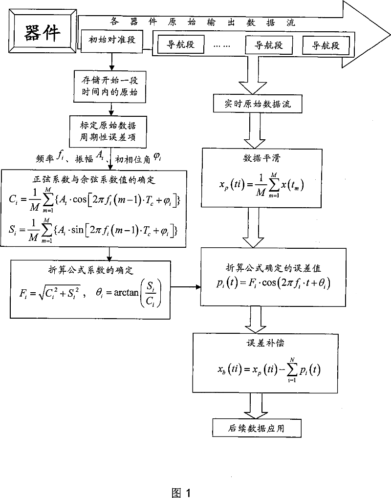
[0006] (1) The main disadvantages of the compensation first and then equalization method: the real-time test frequency is generally high, and the amount of data obtained is large. When performing real-time compensation on the data, it is required to complete a huge amount of calculation in a very short time, and the real-time performance is poor.
[0007] (2) The main disadvantage of the first leveling and then supplementing method: the data smoothing process will affect the frequency stability of the significant periodic error term, resulting in a decrease in compensation accuracy; becomes significant, thereby increasing the workload of compensation and the workload of the processor

Method used


Image

  • Method for fast and accurately compensating component periodic error in strap-down inertial guidance
  • Method for fast and accurately compensating component periodic error in strap-down inertial guidance
  • Method for fast and accurately compensating component periodic error in strap-down inertial guidance

Examples


Embodiment Construction

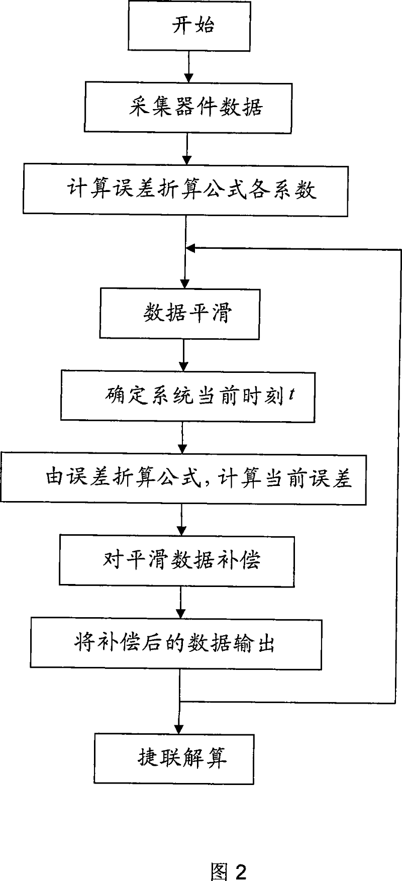
[0064] The embodiments of the present invention are without loss of generality. Taking the output data processing process of a BEI GYROCHIP LCG50 quartz MEMS gyroscope as an example, the compensation process is shown in FIG. 2 . Quartz series MEMS gyroscopes, like other gyroscopes, can continuously output angular velocity information, and their sampling frequency is relatively high. In this embodiment, the typical sampling frequency is 1000 Hz, and the inertial navigation system composed of gyroscopes involves complex navigation parameters. Therefore, the calculation frequency is relatively low, generally around 100Hz. Utilize the step that the present invention carries out real-time compensation to quartz MEMS gyroscope drift periodicity is:

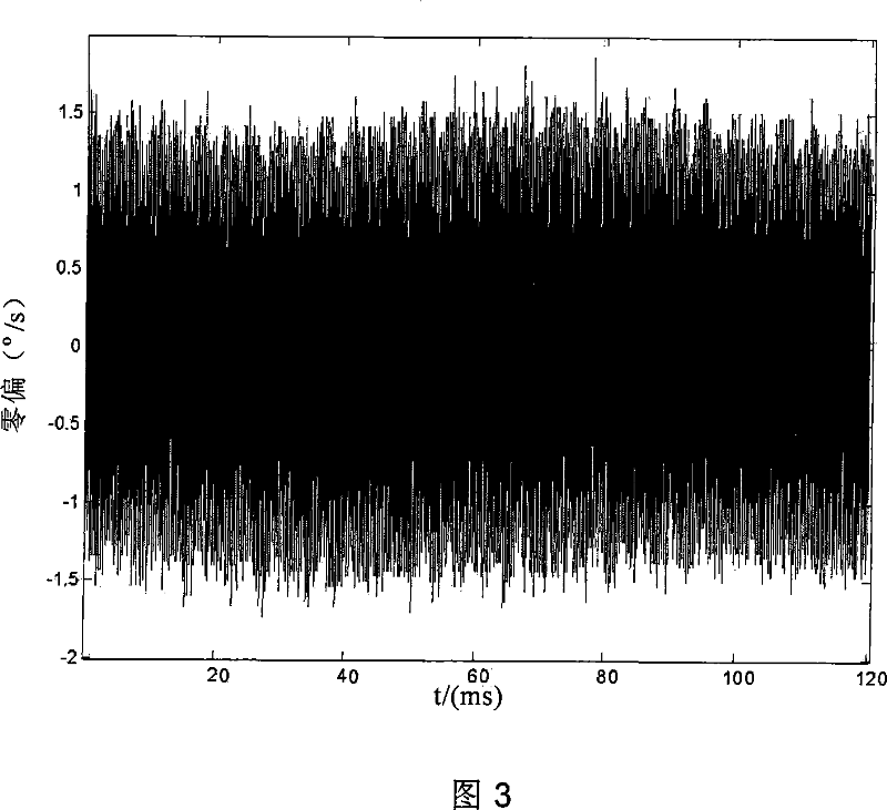
[0065] (1) This embodiment records the drift test data for 120 seconds to verify its compensation effect. Data smoothing adopts 10 data for one smoothing, then in this embodiment, the solution period T s =0.01s, sampling period T c =...


PUM


Abstract

A quick and precise compensation method of the cyclic error of the devices in the strap-down inertial navigation system is provided in the present invention. The margin of error included in the de-calculating data of the navigation system level is converted and compensated in real time by using the error converting formula according to the device level data analyzing result. Wherein the error converting formula is obtained as following steps: the over-sampling original data of the device level in a certain time is analyzed to determine the number and the character parameter of the appreciable periodic error item included in the original data in the measured device level; each coefficient of the error converting formula is calculated according to the deduced formula and is substituted into the error converting formula. The present invention takes full advantage of the periodic error item information included in the device level original data and has advantages of the quantity of calculating in the system level data processing that the compensation precision is high and the l quantity of calculating is small. The present invention is adequate for the periodic error item compensation processing of many kinds of over-sampling data, is especially adequate for the eriodic error item compensation processing of the data calculated by the gyroscope and accelerometer in the inertial navigation system.

Description

technical field [0001] The invention belongs to the technical field of data processing, in particular to a method for compensating periodic errors in drift data of inertial devices such as gyroscopes, and is applicable to the periodic error compensation processing of various oversampling data. Background technique [0002] The inertial navigation system can be divided into three levels: device level, component level and system level. The device level refers to inertial sensitive devices, mainly including three gyroscopes and three accelerometers. Each inertial device can provide sensitive angular velocity and acceleration information in real time. ;The component level refers to the inertial measurement unit composed of inertial devices in a specific way. It performs high-frequency sampling on the inertial devices, and then smoothes each multiple data to supply the system level; the system level refers to the entire inertial navigation system. It is in the navigation computer....

Claims


Application Information

Patent Timeline
IPC IPC(8): G01C21/16
Inventor 房建成张海鹏陈晓光孙科张霄于歌
Owner BEIHANG UNIV
Learn More